Eletechsup Factory store
ND3A05SD 17W Synchronous Boost Regulator Module 3V 3.3V 3.7V to 4.2V 5V DC-DC Converter ND3A05SD for Arduino PI ESP32 Wifi QC PD
ND3A05SD 17W Synchronous Boost Regulator Module 3V 3.3V 3.7V to 4.2V 5V DC-DC Converter ND3A05SD for Arduino PI ESP32 Wifi QC PD
SKU:ND3A05SD_4V2
1000 in stock
Regular price
$2.80
Regular price
$2.80
Sale price
$2.80
Unit price
per
Couldn't load pickup availability
Description:
17W Mini Size High-power DC-DC Boost Converter Module
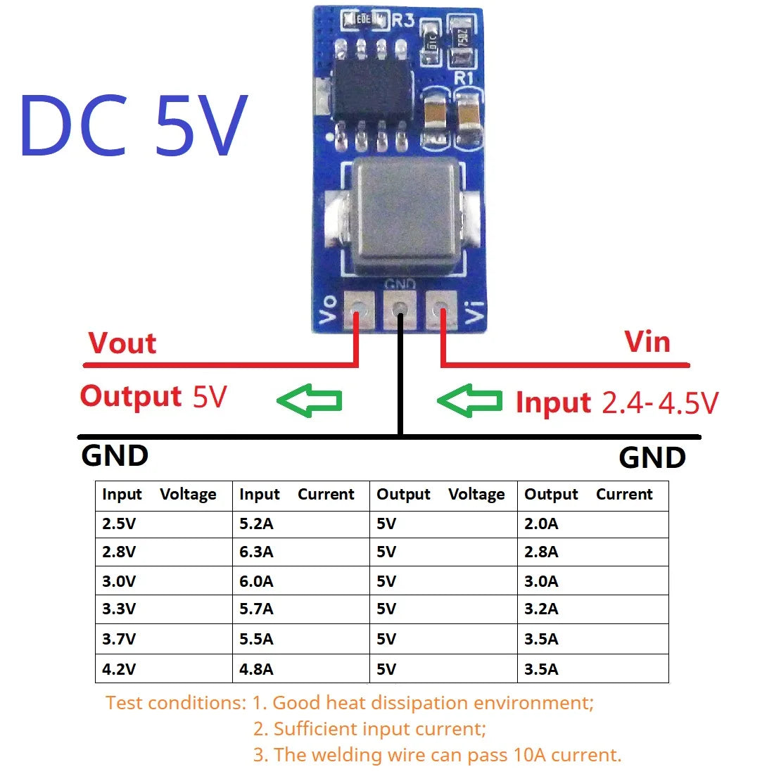
DC 2.4-4V to 4.2V;DC 2.4-4.5V to 5V
Maximum output power 17W(See the table for details)
Maximum input current: 7A(See the table for details)
Maximum output current: 3.5A(See the table for details)
Current Limit Program(0.8-7A,Default 7A)
Quiescent current: about 0.3MA
Efficiency : Up to 91%
Switching Frequency : 500KHz fixed
Overcurrent protection,Short circuit protection,Over temperature protection
Operating Ambient Temperature : -40 to 85 °C
Storage Temperature : -55 to 150°C
Size : 21 x 11 x 6mm
Weight : 2.1g
Pin description:
Vi : Input positive(+)
GND : Input and Output negative(GND/-)
Vo : Output positive(+)
Attention :
This is a high-power boost module. Please pay attention to the following when using:
1 The power supply must be sufficient. If the module needs to output 17W power, the power supply must be greater than 25W.
2 The power and boost module leads must be thick enough (can pass 10A) and soldered well.
3 Use a multimeter to directly measure the ''Vi GND'' port to determine if the power is sufficient. If the voltage is lower than the power supply 1V, the power supply is insufficient or there is no good connection.
4 Input voltage can not be greater than the maximum input range
5 Output power can not be greater than the maximum load for a long time
6 Input power must be greater than the output power, because the power consumption of the module itself
Applications:
for QC PD charger
for 3.7V li-on Lipo Lithium Battery 18650
PTZ CCTV IP camera
Smart home / home automation
WIFI Router Switch Network equipment
LED Motor Driver
For short-term maximum input and output current, please refer to the table below. For long-term use, please add a heat sink or reduce the output current to 60%.

When used to drive inductive loads or motors, please pay attention to the following:
1 Please note that the starting current of the motor is greater than 3 times the rated current.
2 Please ensure that the power supply is sufficient.
3 Please connect a diode or drive circuit between the module and the motor.

Changing the value of the R3 resistor changes the maximum input current threshold.
Maximum input current(A)= 180/R3(KΩ)
Changing the value of the R1 resistor changes the output voltage.
Vout(V)=0.6*(R1/10+1)