1
/
of
7
Eletechsup Factory store
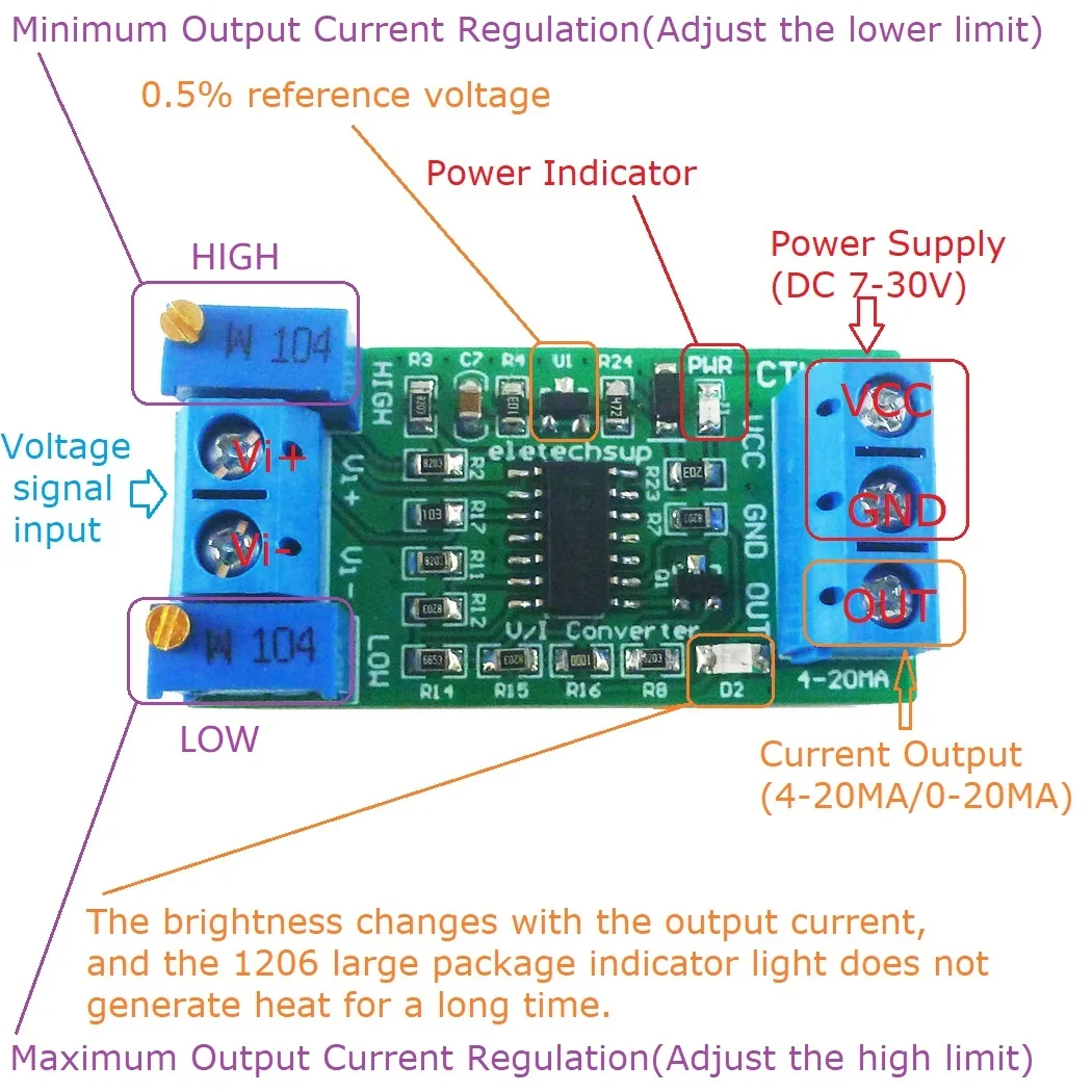
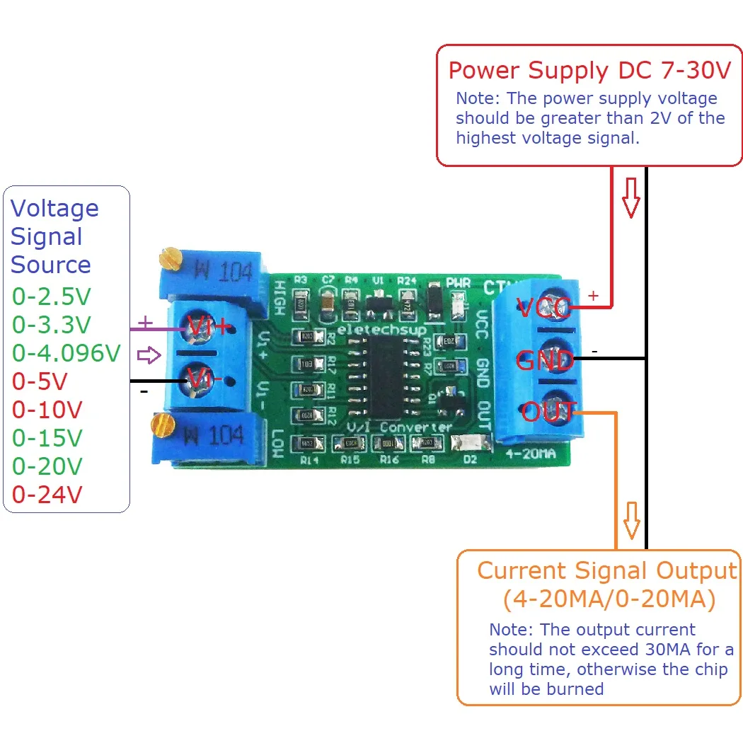
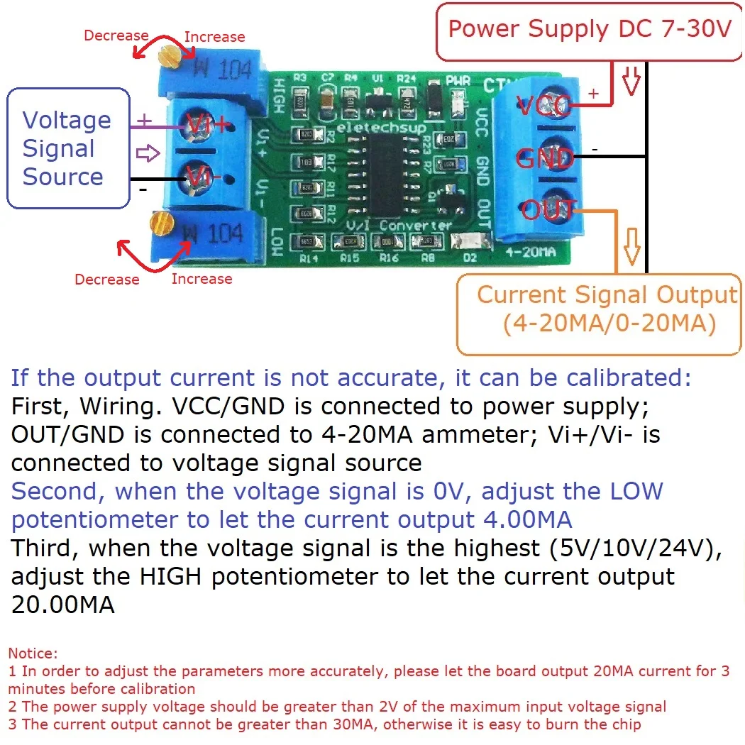
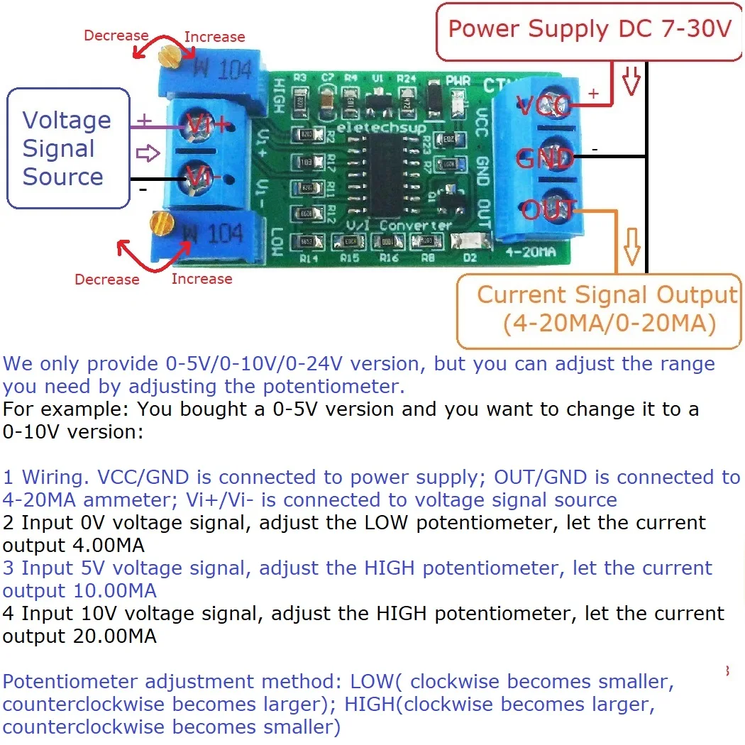
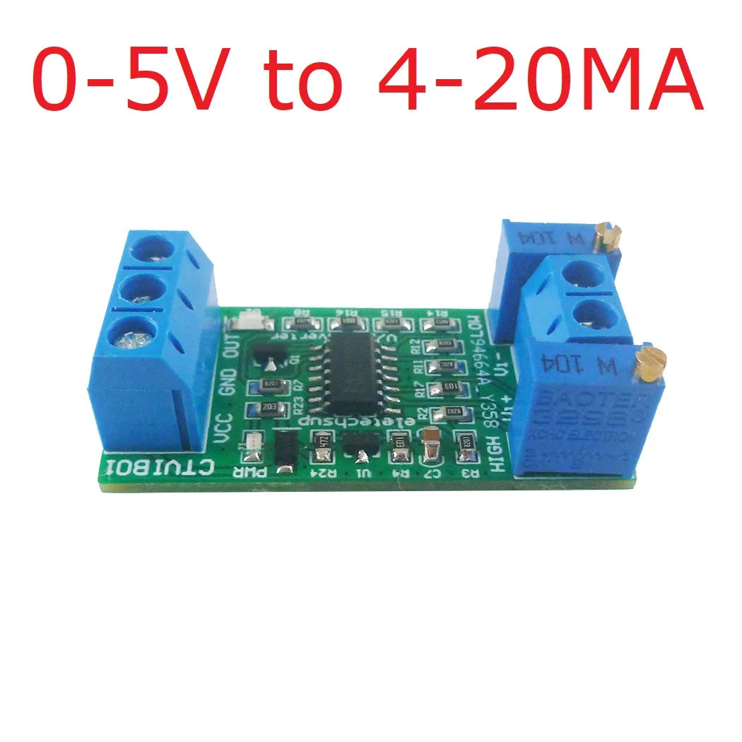
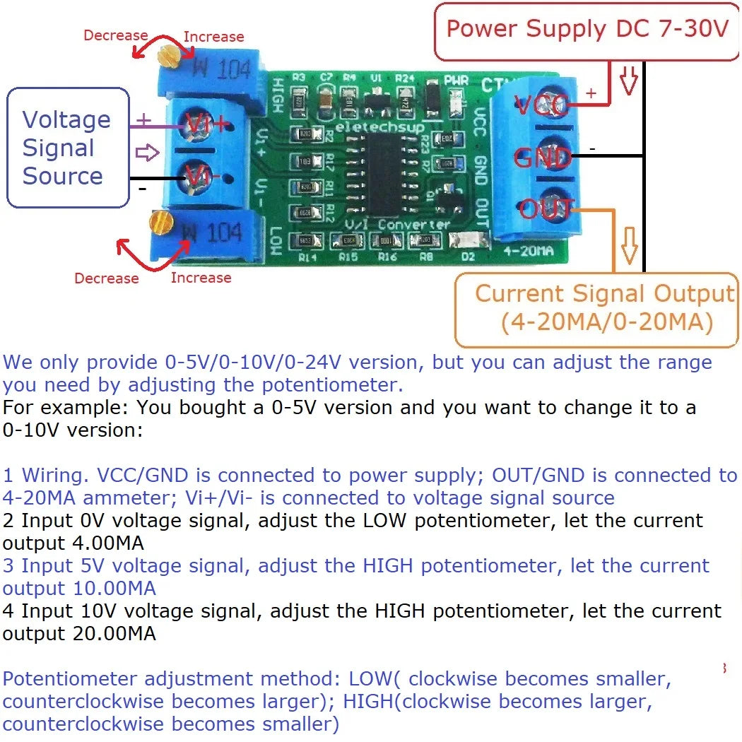
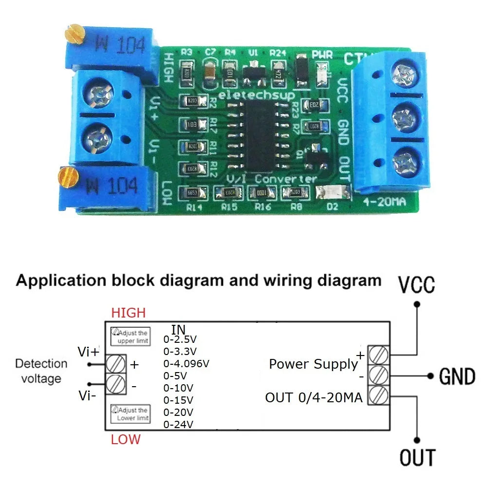
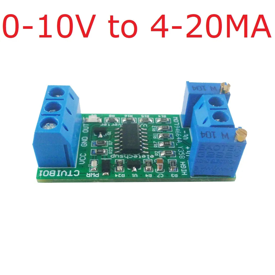
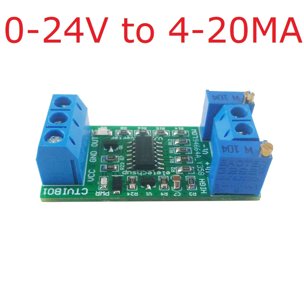
CTVIB01 0-5V/0-10V to 4-20mA/0-20mA Voltage to Current Analog IO Module Transmitter V/I Linear Converter for PLC RS485 Sensor
Regular price
$3.50 USD
Regular price
$3.50 USD
Sale price
$3.50 USD
Unit price
/
per
Couldn't load pickup availability
Product Name:
0-5V 10V 24V to 4-20mA Range Adjustable Voltage to Current Transmitter Linear V/I Converter Module
Packing list:
1PCS
0-5V/10V/24V to 4-20mA V/I Converter Module
(Specific according to the version and quantity you choose)

Description:
1 Working voltage: DC 7-30V (the power supply voltage must be greater than the input voltage by more than 2V)
2 Working current: 10-30MA (related to the output current)
3 Voltage signal input range: 0-5V/0-10V/0-24V.
4 current signal output range: 4-20MA
5 Accuracy: 1%
6 Size: 42*21*14mm
7 Weight: 8 grams
2 Working current: 10-30MA (related to the output current)
3 Voltage signal input range: 0-5V/0-10V/0-24V.
4 current signal output range: 4-20MA
5 Accuracy: 1%
6 Size: 42*21*14mm
7 Weight: 8 grams
This voltage-to-current module can convert 0-5V/0-10V/0-24V voltage into 4-20MA output.
It can also be adjusted to any range within 24V by adjusting the potentiometer on the board, such as:
0-2.5V
0-3.3V
0-4.096V
0-5V
0-10V
0-15V
0-20V
0-24V
Notice:
1. In order to adjust the parameters more accurately, please let the board output 20MA current for 3 minutes before calibration
2. The power supply voltage must be greater than the input voltage by 2V or more
3 .The current output cannot be greater than 30MA, otherwise it is easy to burn the chip
4. Potentiometer adjustment method: LOW: clockwise becomes smaller, counterclockwise becomes larger; HIGH: clockwise becomes larger, counterclockwise becomes smaller
Onboard resources:
Wiring Diagram:
Demo : https://youtu.be/7BiH6o17bG0
If the output current is not accurate, it can be calibrated:
1. Wire according to the above diagram. VCC/GND is connected to power supply; OUT/GND is connected to 4-20MA ammeter; Vi+/Vi- is connected to voltage signal source
2. Input 0V voltage signal, adjust the LOW potentiometer, let the current output 4.00MA
3. Adjust the voltage signal to the highest level (5V/10V/24V), adjust the HIGH potentiometer, and let the current output 20.00MA
Demo : https://youtu.be/zL1KJdYkfCE
We only provide 0-5V/0-10V/0-24V version, but you can adjust the range you need by adjusting the potentiometer.
For example: You bought a 0-5V version and you want to change it to a 0-10V version:
1. Wire according to the above diagram. VCC/GND is connected to power supply; OUT/GND is connected to 4-20MA ammeter; Vi+/Vi- is connected to voltage signal source
2. Input 0V voltage signal, adjust the LOW potentiometer, let the current output 4.00MA
3. Input 5V voltage signal, adjust the HIGH potentiometer, let the current output 10.00MA
4. Input 10V voltage signal, adjust the HIGH potentiometer, let the current output 20.00MA
It can also be adjusted to any range within 24V by adjusting the potentiometer on the board, such as:
0-2.5V
0-3.3V
0-4.096V
0-5V
0-10V
0-15V
0-20V
0-24V
Notice:
1. In order to adjust the parameters more accurately, please let the board output 20MA current for 3 minutes before calibration
2. The power supply voltage must be greater than the input voltage by 2V or more
3 .The current output cannot be greater than 30MA, otherwise it is easy to burn the chip
4. Potentiometer adjustment method: LOW: clockwise becomes smaller, counterclockwise becomes larger; HIGH: clockwise becomes larger, counterclockwise becomes smaller
Onboard resources:


Demo : https://youtu.be/7BiH6o17bG0
If the output current is not accurate, it can be calibrated:
1. Wire according to the above diagram. VCC/GND is connected to power supply; OUT/GND is connected to 4-20MA ammeter; Vi+/Vi- is connected to voltage signal source
2. Input 0V voltage signal, adjust the LOW potentiometer, let the current output 4.00MA
3. Adjust the voltage signal to the highest level (5V/10V/24V), adjust the HIGH potentiometer, and let the current output 20.00MA

Demo : https://youtu.be/zL1KJdYkfCE
We only provide 0-5V/0-10V/0-24V version, but you can adjust the range you need by adjusting the potentiometer.
For example: You bought a 0-5V version and you want to change it to a 0-10V version:
1. Wire according to the above diagram. VCC/GND is connected to power supply; OUT/GND is connected to 4-20MA ammeter; Vi+/Vi- is connected to voltage signal source
2. Input 0V voltage signal, adjust the LOW potentiometer, let the current output 4.00MA
3. Input 5V voltage signal, adjust the HIGH potentiometer, let the current output 10.00MA
4. Input 10V voltage signal, adjust the HIGH potentiometer, let the current output 20.00MA

Share


