


Eletechsup Factory store
2pcs DC 3.3V 5V 12V 6 Digitals Blue LED Module 6 bits indicator Diy kit Board for MCU Pro Breadboard 3D printer LCD Digital Tube
2pcs DC 3.3V 5V 12V 6 Digitals Blue LED Module 6 bits indicator Diy kit Board for MCU Pro Breadboard 3D printer LCD Digital Tube
Regular price
$1.99 USD
Regular price
$1.99 USD
Sale price
$1.99 USD
Unit price
per
Couldn't load pickup availability
Product Name:2pcs DC 3.3V 5V 12V 6 Digitals Blue LED Module 6 bits indicator Diy kit Board for MCU Pro Breadboard 3D printer LCD Digital Tube
Packing list:
2 pcs 6 bit
Blue
color
3.3V 5V 12V
LED's Board
Description:
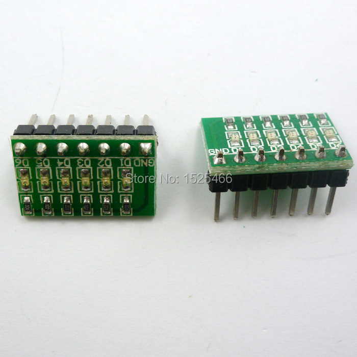
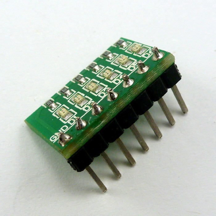
2.54MM PIN 6 Digitals LED Board ,Can be inserted directly into for Arduiuo
UNO MEGA2560 DUE
Board
,Ideal for linking up to your Arduiuo UNO Pro Mini Nano Mega2560 DUE
Development
Board
etc,or others MCU
Embedded development board
(AVR STM32 ARM7 ARM9 PIC C8051 C51 STC MSP430 FPGA/CPLD etc.)
,Ideal for linking up to your Arduiuo UNO Pro Mini Nano Mega2560 DUE
Development
Board
etc,or others MCU
Embedded development board
(AVR STM32 ARM7 ARM9 PIC C8051 C51 STC MSP430 FPGA/CPLD etc.)
1. 6 Bits
Blue
Common Cathode LEDs(Active high level).
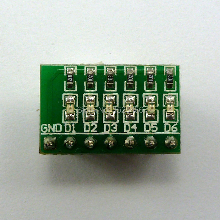
2.2.54mm 7 PIN Input
3. 1K ohm Limiting resistor
4. Power Supply Voltage: 3-12V;
5. Size: 17.78MM x 11.43MM.
3. 1K ohm Limiting resistor
4. Power Supply Voltage: 3-12V;
5. Size: 17.78MM x 11.43MM.
PCB:
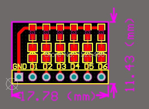
Circuit schematics :

Connection with Arduiuo(Only 6 bit LED's Board ,Does not include UNO R3):
Arduiuo uno/mega2560 Code 1pcs
//******************************************************//
/*
Arduiuo_6led
This example code is in the public domain.
*/
// give it a name:
int D1 = 13;
int D2 = 12;
int D3 = 11;
int D4 = 10;
int D5 = 9;
int D6 = 8;
// the setup routine runs once when you press reset:
void setup() {
// initialize the digital pin as an output.
pinMode(D1, OUTPUT);
pinMode(D2, OUTPUT);
pinMode(D3, OUTPUT);
pinMode(D4, OUTPUT);
pinMode(D5, OUTPUT);
pinMode(D6, OUTPUT);
}
// the loop routine runs over and over again forever:
void loop() {
digitalWrite(D1, HIGH); // turn the LED on (HIGH is the voltage level)
delay(200); // wait for a 200 Millisecond
digitalWrite(D1, LOW); // turn the LED off by making the voltage LOW
digitalWrite(D2, HIGH); // turn the LED on (HIGH is the voltage level)
delay(200); // wait for a Millisecond
digitalWrite(D2, LOW); // turn the LED off by making the voltage LOW
digitalWrite(D3, HIGH); // turn the LED on (HIGH is the voltage level)
delay(200); // wait for a Millisecond
digitalWrite(D3, LOW); // turn the LED off by making the voltage LOW
digitalWrite(D4, HIGH); // turn the LED on (HIGH is the voltage level)
delay(200); // wait for a Millisecond
digitalWrite(D4, LOW); // turn the LED off by making the voltage LOW
digitalWrite(D5, HIGH); // turn the LED on (HIGH is the voltage level)
delay(200); // wait for a Millisecond
digitalWrite(D5, LOW); // turn the LED off by making the voltage LOW
digitalWrite(D6, HIGH); // turn the LED on (HIGH is the voltage level)
delay(200); // wait for a Millisecond
digitalWrite(D6, LOW); // turn the LED off by making the voltage LOW
}
//******************************************************//
Arduiuo uno/mega2560 Code(
Use two LED board)
//******************************************************//
/*
Arduiuo_6led
This example code is in the public domain.
*/
// LED Board 1
int D1 = 13;
int D2 = 12;
int D3 = 11;
int D4 = 10;
int D5 = 9;
int D6 = 8;
// LED Board 2
int D11 = 1;
int D12 = 2;
int D13 = 3;
int D14 = 4;
int D15 = 5;
int D16 = 6;
int GND = 7;//Common Cathode
void setup() {
// initialize the digital pin as output.
pinMode(D1, OUTPUT);
pinMode(D2, OUTPUT);
pinMode(D3, OUTPUT);
pinMode(D4, OUTPUT);
pinMode(D5, OUTPUT);
pinMode(D6, OUTPUT);
pinMode(D11, OUTPUT);
pinMode(D12, OUTPUT);
pinMode(D13, OUTPUT);
pinMode(D14, OUTPUT);
pinMode(D15, OUTPUT);
pinMode(D16, OUTPUT);
pinMode(GND, OUTPUT);
digitalWrite(GND, LOW);
}
// the loop routine runs over and over again forever:
void loop() {
digitalWrite(D1, HIGH); // turn the LED on (HIGH is the voltage level)
delay(200); // wait for a 200 Millisecond
digitalWrite(D1, LOW); // turn the LED off by making the voltage LOW
digitalWrite(D2, HIGH); // turn the LED on (HIGH is the voltage level)
delay(200); // wait for a Millisecond
digitalWrite(D2, LOW); // turn the LED off by making the voltage LOW
digitalWrite(D3, HIGH); // turn the LED on (HIGH is the voltage level)
delay(200); // wait for a Millisecond
digitalWrite(D3, LOW); // turn the LED off by making the voltage LOW
digitalWrite(D4, HIGH); // turn the LED on (HIGH is the voltage level)
delay(200); // wait for a Millisecond
digitalWrite(D4, LOW); // turn the LED off by making the voltage LOW
digitalWrite(D5, HIGH); // turn the LED on (HIGH is the voltage level)
delay(200); // wait for a Millisecond
digitalWrite(D5, LOW); // turn the LED off by making the voltage LOW
digitalWrite(D6, HIGH); // turn the LED on (HIGH is the voltage level)
delay(200); // wait for a Millisecond
digitalWrite(D6, LOW); // turn the LED off by making the voltage LOW
digitalWrite(D16, HIGH); // turn the LED on (HIGH is the voltage level)
delay(200); // wait for a Millisecond
digitalWrite(D16, LOW); // turn the LED off by making the voltage LOW
digitalWrite(D15, HIGH); // turn the LED on (HIGH is the voltage level)
delay(200); // wait for a Millisecond
digitalWrite(D15, LOW); // turn the LED off by making the voltage LOW
digitalWrite(D14, HIGH); // turn the LED on (HIGH is the voltage level)
delay(200); // wait for a Millisecond
digitalWrite(D14, LOW); // turn the LED off by making the voltage LOW
digitalWrite(D13, HIGH); // turn the LED on (HIGH is the voltage level)
delay(200); // wait for a Millisecond
digitalWrite(D13, LOW); // turn the LED off by making the voltage LOW
digitalWrite(D12, HIGH); // turn the LED on (HIGH is the voltage level)
delay(200); // wait for a Millisecond
digitalWrite(D12, LOW); // turn the LED off by making the voltage LOW
digitalWrite(D11, HIGH); // turn the LED on (HIGH is the voltage level)
delay(200); // wait for a 200 Millisecond
digitalWrite(D11, LOW); // turn the LED off by making the voltage LOW
}
//******************************************************//


