Eletechsup Original Factory Official Store
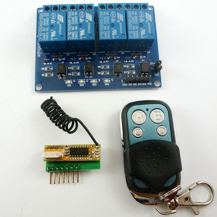
CJ018 433M 4Ch RF Wireless Remote Control Switch Relay Board for Arduno MEGA2560
CJ018 433M 4Ch RF Wireless Remote Control Switch Relay Board for Arduno MEGA2560
SKU:CJ018*1+CJ003*1+YC064*1
1000 in stock
Couldn't load pickup availability
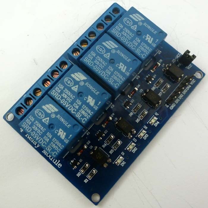
1 PCS DC5V 4 Channel Arduino Relay Board;

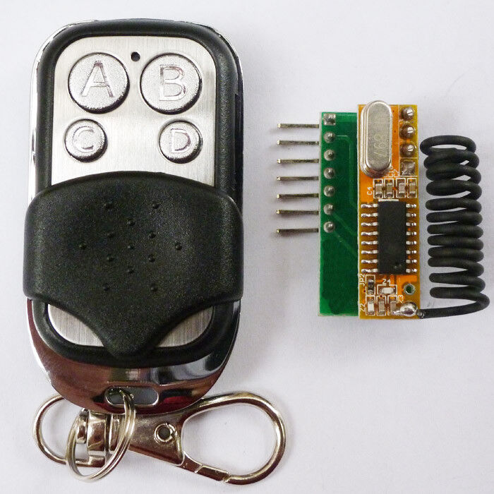
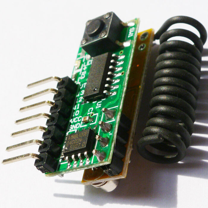
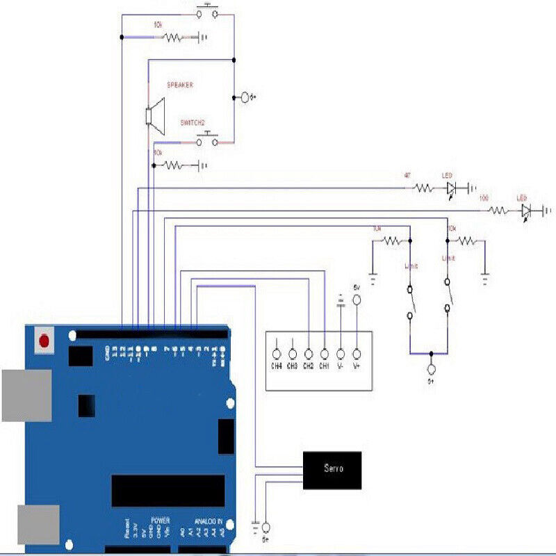
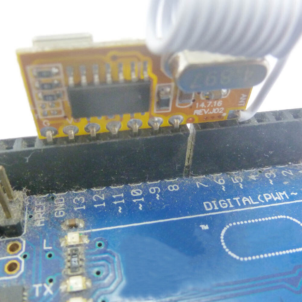
| Receiver module | UNO/MEGA2560 |
| GND | GND |
| VCC | 13 |
| I0 | 12 |
| I1 | 11 |
| I2 | 10 |
| I3 | 9 |
| VT | 8 (You can ignore) |
//Author: cantone-electonics
//More information welcome to :
//Arduino 1.0.4
//Arduino uno R3
//Arduino 4 channel Wireless Controller
int VCC = 13;//
int I0 = 12;
int I1 = 11;
int I2 = 10;
int I3 = 9;
int VT = 8;
int Relay1 = A0;
int Relay2 = A1;
int Relay3 = A2;
int Relay4 = A3;
int InputState = 1; // variable for reading the input status
// the setup routine runs once when you press reset:
void setup() {
// initialize the digital pin
pinMode(VCC, OUTPUT);
pinMode(I0, INPUT);
pinMode(I1, INPUT);
pinMode(I2, INPUT);
pinMode(I3, INPUT);
// pinMode(VT, INPUT);
pinMode(Relay1, OUTPUT);
pinMode(Relay2, OUTPUT);
pinMode(Relay3, OUTPUT);
pinMode(Relay4, OUTPUT);
digitalWrite(Relay1, HIGH);
digitalWrite(Relay2, HIGH);
digitalWrite(Relay3, HIGH);
digitalWrite(Relay4, HIGH);
digitalWrite(VCC, HIGH);//AS VCC
//Activate input pin internal pull-up resistors
digitalWrite(I0, HIGH);
digitalWrite(I1, HIGH);
digitalWrite(I2, HIGH);
digitalWrite(I3, HIGH);
// digitalWrite(VT, HIGH);
delay(2000);//Waiting for rf receiver module startup
}
// the loop routine runs over and over again forever:
void loop() {
InputState = digitalRead(I0);
if(InputState==0) digitalWrite(Relay1, HIGH); else digitalWrite(Relay1, LOW);
InputState = digitalRead(I1);
if(InputState==0) digitalWrite(Relay2, HIGH); else digitalWrite(Relay2, LOW);
InputState = digitalRead(I2);
if(InputState==0) digitalWrite(Relay3, HIGH); else digitalWrite(Relay3, LOW);
InputState = digitalRead(I3);
if(InputState==0) digitalWrite(Relay4, HIGH); else digitalWrite(Relay4, LOW);
}