Skip to product information
1 of 9

Eletechsup Original Factory Official‌ Store

RF22A04 433M forArduno Remote Control UART PC USB RF Wireless Relay Controller PT2262 MC

RF22A04 433M forArduno Remote Control UART PC USB RF Wireless Relay Controller PT2262 MC

SKU:RF22A04*1+BX003*1

1000 in stock

Regular price $26.98
Regular price $26.98 Sale price $26.98
Sale Sold out
Kit number : RT410
 
Qty:
 
1 PCS 433M Wireless transmitter module(Does not include Ardiuno UNO);
1 PCS 433M 4 channels relay switch;


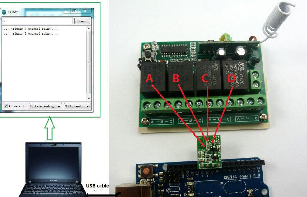
Wireless transmitter module connected with Ardiuno uno(replace PT2262 Remote Keyfob
USE:


Software control:
How to use:send ''a'' trigger A channel relay,send ''b'' trigger A channel relay,Etc.


Ardiuno core fragment(complete code through ebay message Request):
 
//Author: cantone-electonics
//Ardiuno 1.0
//Ardiuno R3
//Making a wireless remote control with Ardiuno
 
 
...
 
//send:8 Address Bits, 4 Data Bits, Sync bit
void send-data()
 
 
void setup() {
// initialize the LED pin as an output:
pinMode(ledPin, OUTPUT);
// initialize the encoder DOUT pin as an output
pinMode(data-out, OUTPUT);
 
Serial.begin(9600);
 
}
 
void loop()
{
...
 
while(1)
{
//get key from pc serial port
while (Serial.available() > 0)
{
keydata = Serial.read();
receive flag = 1;
delay(2);
}
 
if(receive flag == 1)//if get key,send key
{
 
receiv flag = 0;
 
if((keydata == 'a') || (keydata == 'A'))//trigger A channel relay.
{
Temporary[2] = 0xC0;// 0xC0 is A button key
digitalWrite(ledPin, HIGH);//Turn on led
send data();//send code word
Serial.println(''.....trigger A channel relay.....'');
}
else if((keydata == 'b') || (keydata == 'B'))//trigger B channel relay.
{
Temporary[2] = 0x30;// 0x30 is B button key
digitalWrite(ledPin, HIGH);//Turn on led
send data();//send code word
Serial.println(''.....trigger B channel relay.....'');
}
else if((keydata == 'c') || (keydata == 'C'))//trigger C channel relay.
{
Temporary[2] = 0x0C;// 0x0C is C button key
digitalWrite(ledPin, HIGH);//Turn on led
send data();//send code word
Serial.println(''.....trigger C channel relay.....'');
 
}
else if((keydata == 'd') || (keydata == 'D'))//trigger D channel relay.
{
Temporary[2] = 0x03;// 0x03 is D button key
digitalWrite(ledPin, HIGH);//Turn on led
send data();//send code word
Serial.println(''.....trigger D channel relay.....'');
}
 
...
 
}
}
 

Description (Click on the link below):

receiver Features:


Typical applications:
DC 12V Home lighting system
Remote control switch
Smart Home / Home Automation
LED lighting
Fluorescent lamp
DC 12 DC Motor,RS360
 
Wiring Diagram 1:
DC 12V control circuit,Wiring diagram below. ''LOAD'' may be LED lights, fans, motors and other DC 12V


Wiring Diagram 2:

DC 1-110V OR AC 85-265V control circuit,Wiring diagram below(Note:If not DC 12V load, need another DC 12V power supply). ''LOAD'' may be LED lights, fans, motors and other DC AC equipment


Wiring Diagram 3:
All kinds of motor reversing control: DC 1-110V or AC 85-265V DC/AC Motor


Product Name : DC 12V 4CH 433MHz Delay RF Wireless Relay Controller For PT2262 EV1527 Encoder
 
Module No.: CE-RF22A04

Packing list:

1 PCS 433M DC 12V 4 Channel Multifunction Wireless Controller
 
Features:
 
1 Operating voltage : DC 12V
2 Operating Current: Standby current (all relays closed) 15MA, 1 relay open 42MA, 2 relays open 62MA, 3 relays open 94MA, 4 relays open 121MA
3 Operating frequency: 433.92M;
 
4 Receiver sensitivity : -108dBm
 
5 Decode : learning code, can be adapted EV1527 / PT2262(Click here)and compatible remote control, you can store up to 8 remote control
 
6 Work mode : Non-locking (Momentary is defult),Self-locking (Toggle),Inter-locking (Latch), Delay; Delay adjustable from 0.1 to 100 seconds, 0.1 seconds Resolution.
7 Size(Including housing)75*54*28mm
8 Weight: 77g
9 Relay Maximum load(Recommended<5A):10A/250VAC,10A/125VAC,10A/30VDC, 10A/28VDC ,10A/12VDC
Advantage :

1: Receiver Mother board have a learning key , if the remote is lost , must buy EV1527 OR Pt2262 remotes to re-learn;


Work mode

Delay mode user guide :
 
1 In delay mode(Mode 3),with a suitable screwdriver and gently rotating adjustable resistance;Clockwise, increasing delay,Counter-clockwise, the delay is reduced
 
2 Delay adjustable from 0.1 to 100 seconds, 0.1 seconds Resolution.
 
Glossary:

NO : Relay normally open contact

COM : Relay common contact

NC : Relay normally closed contact

Open : NO connection COM, NC disconnect COM

Close : NO disconnect COM, NC connection COM

Momentary : Press the Transmitter button A, the receiver Channel 1 is Open, release button A; the receiver Channel 1 is Close, the same as B ,Every Channel is Independent ;

Toggle : Press transmitter button A for 1 time , the receiver Channel 1 is Open, press button A again, the receiver Channel 1 is Close, the same as B. Every Channel is Independent ;

Latched : Press transmitter button A, the receiver Channel 1 is Open, the Channel 2 is Close.

Press transmitter button B, the receiver Channel 2 is Open, the Channel 1 is Close.

Delay : Press the Transmitter button A, the receiver Channel 1 is Open,After a set time delay, the receiver Channel 1 is Close, the same as B ,Every Channel is Independent;

If during the delay, press the button of Transmitter, delay start again; if the delay period, press and hold the button of Transmitter 3-4 seconds, the receiver controller stops the delay, the relay Close


Adapter remote control (learning remote control):


Under normal operating mode, LED will be lit, when receives a valid remote control (EV1527 / PT2262) button values, LED flashes


Clean code: press the button and held down, LED off, LED will light about 8 seconds later, clean code is completed (Note: After performing clean code previously stored remote control value does not exist)


Step 1 (into the learning mode): Press the button (about 1 second), LED off;


Step 2 (adapter channel 1): Then press the first button on the remote control, LED flashes four times off, then learning the first button value


Step 3 (Adaptation Channel 2): Then press the second button on the remote control, LED flashes four times brighter, then learned two key values


Step 4 (Adaptation Channel 3): Then press the third button on the remote control, LED flashes four times brighter, then learned two key values


Step 5 (Adaptation Channel 4): Then press the fourth button on the remote control, LED flashes four times brighter, then learned two key values

Transmitter :


Application on Atmega8 AVR microcontrollers :


Item Description


Technical Data :
 
Transmitter module No.: BX-TM01 -433 ;
Operating frequency (MHz): 433.92MHz ;
Transmit power: more than 10mW;
Operating Voltage (V): DC 3-12V ;
Low transmit of the static power consumption is current consumption : 10 mA (No transmit No current consumption);
SAW Frequency stability :±75KHZ;
Data transfer rate : 3 kb/s ;
Operating temperature: -20   ~ +60  ;
Size : 11x16x5.5MM;
Type of Output: TTL;
 
Typical Applications
Automotive RKE systems
Automotive alarm systems
Automotive immobilizers
Gate and garage door openers
Burglar alarm systems


We provide ARDUINO sample code , please contact after your order at Ebay message . 


Qty:
 
1 PCS 433M Wireless transmitter module(Does not include Arduino UNO);
1 PCS 433M 4 channels relay switch;


Wireless transmitter module connected with  Arduino uno(replace PT2262 Remote Keyfob
 
USE: 


Software control: 
How to use:send "a" trigger A channel relay,send "b" trigger A channel relay,Etc.
 
arduino core fragment(complete code through ebay message  Request):
  
//Author: cantone-electonics
//Arduino 1.0
//Arduino uno R3
//Making a wireless remote control with arduino
 
  
...
 
//send:8 Address Bits, 4 Data Bits, Sync bit
void send_data()
 
 
void setup() {
  // initialize the LED pin as an output:
  pinMode(ledPin, OUTPUT); 
   // initialize the encoder DOUT pin as an output
  pinMode(data_out, OUTPUT);
 
  Serial.begin(9600);
 
}
 
void loop()
{
  ...
  
  while(1)
  {
    //get key from pc serial port
    while (Serial.available() > 0) 
    {
        keydata = Serial.read();
        receive_flag = 1;
        delay(2);
    }
   
    if(receive_flag == 1)//if get key,send key
    {
     
    receive_flag = 0;
   
    if((keydata == 'a') || (keydata == 'A'))//trigger A channel relay.
    {
      Temporary[2] = 0xC0;// 0xC0 is A button key
      digitalWrite(ledPin, HIGH);//Turn on led
      send_data();//send code word
       Serial.println(".....trigger A channel relay.....");
    }
    else if((keydata == 'b') || (keydata == 'B'))//trigger B channel relay.
    {
      Temporary[2] = 0x30;// 0x30 is B button key
      digitalWrite(ledPin, HIGH);//Turn on led
      send_data();//send code word
      Serial.println(".....trigger B channel relay.....");
    }
     else if((keydata == 'c') || (keydata == 'C'))//trigger C channel relay.
     {
      Temporary[2] = 0x0C;// 0x0C is C button key
      digitalWrite(ledPin, HIGH);//Turn on led
      send_data();//send code word
      Serial.println(".....trigger C channel relay.....");
     
     }
     else if((keydata == 'd') || (keydata == 'D'))//trigger D channel relay.
     {
      Temporary[2] = 0x03;// 0x03 is D button key
      digitalWrite(ledPin, HIGH);//Turn on led
      send_data();//send code word
      Serial.println(".....trigger D channel relay.....");
     }
    
    ...
  
  }
View full details