Eletechsup Original Factory Official Store
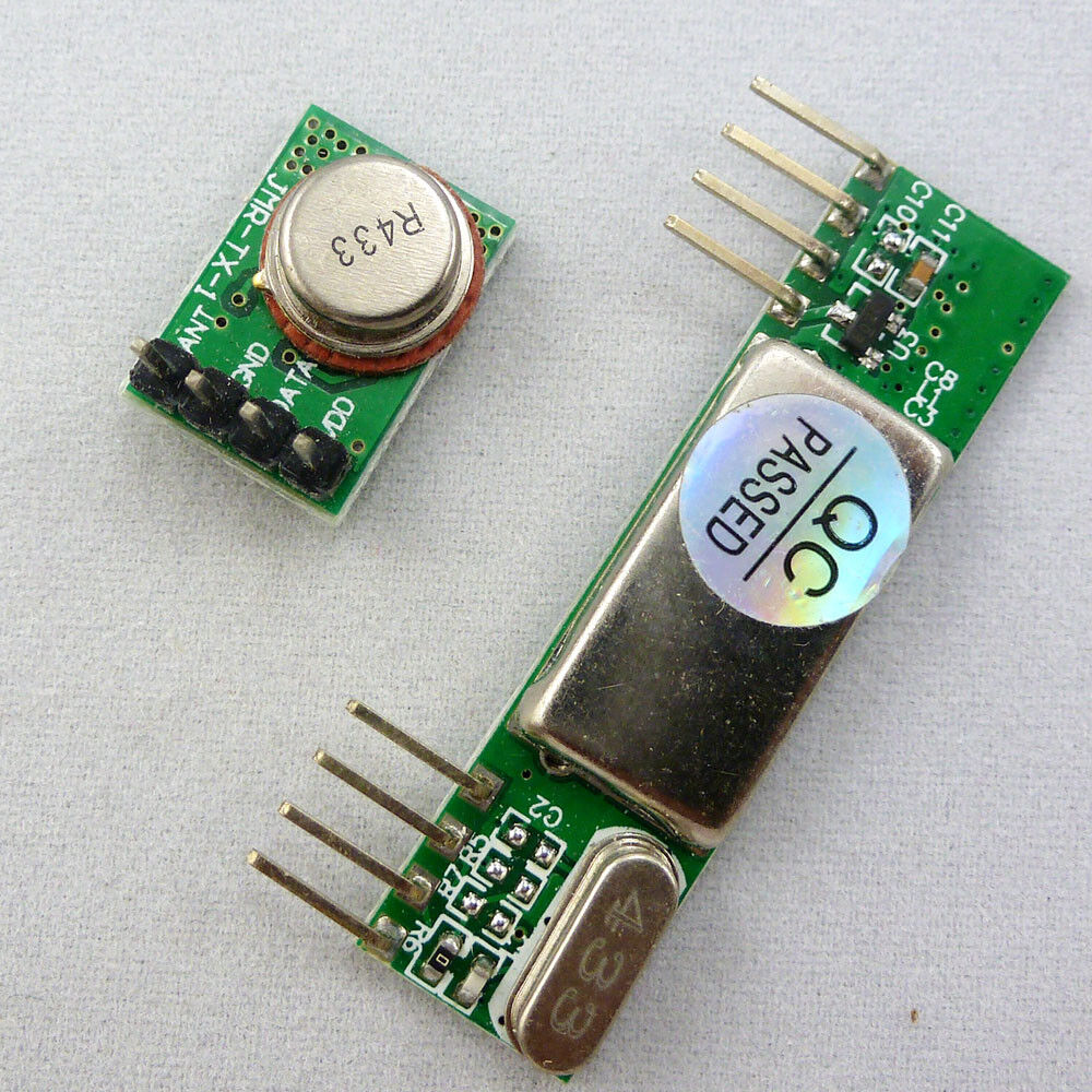
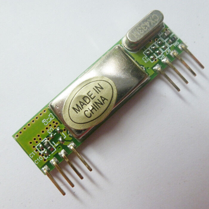
ASK AM RF Super-heterodyne Remote Receiver RX Module 433MHZ -112dBm RX TX
ASK AM RF Super-heterodyne Remote Receiver RX Module 433MHZ -112dBm RX TX
SKU:BX005*1+BX003*1
1008 in stock
Couldn't load pickup availability
Item Description :
Technical Data :
Operating frequency (MHz): 433.92MHz ;
Item Description :
Operating Voltage (V): DC 3-12V
low transmit of the static power consumption is current consumption : 10 mA ( No transmit No current consumption);
Data transfer rate : 3 kb/s
Sometimes in embedded design you may want to go wireless. Might be you will want to log various readings of remotely placed sensors, or simply build a remote control for robot or car alarm system.
I have constructed two separate circuits for testing on Atmega8 microcontrollers.
Transmitter
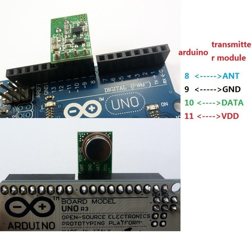
As you can see I have used one LED for indicating RF activity. Ok enough about hardware part – actually there is nothing more to say – circuits are simple.
Lets move on to software part. Radio transmission is a bit more complicated than wired communications because you never know what radio signals are present on air. So all matters how transmitted signal is encoded. And this is a part where you have many choices: use hardware encoding like USART or write your own based on one of many ending methods like NRZ, Manchester etc. In my example I have used AVR USART module to form data packs. Using hardware encoders solves many problems like synchronization, start and stop, various signal checks. But as long as I was practising you cannot rely on plain USART signal. Here you can actually improvize by adding various checks and so on.
I decided to form 4 byte data packages in order to send one byte information. These include:
-
one dummy synchronization byte (10101010);
-
one address byte – in case there are more receivers(or transmitters);
-
one data byte;
-
and checksum which is actually a sum of address and data(address+data).
Why did I use a dummy byte at the beginning of package. Simply I noticed, that when transmitter doesn't transmit any data – receiver catches various noises that come from power supply or other sources because receiver likes adjust its input gain depending on input signal level. First byte tunes receiver to accept normal signal after then address byte, data and checksum can be read more reliably. Probably with different transmission modules you may exclude this dummy byte.
Ttransmitter program for AVR Atmega8:
#include
#include
#ifndef F_CPU
//define cpu clock speed if not defined
#define F_CPU 8000000
#endif
//set desired baud rate
#define BAUDRATE 1200
//calculate UBRR value
#define UBRRVAL ((F_CPU/(BAUDRATE*16UL))-1)
//define receive parameters
#define SYNC 0XAA// synchro signal
#define RADDR 0x44
#define LEDON 0x11//switch led on command
#define LEDOFF 0x22//switch led off command
void USART_Init(void)
{
//Set baud rate
UBRRL=(uint8_t)UBRRVAL; //low byte
UBRRH=(UBRRVAL>>8); //high byte
//Set data frame format: asynchronous mode,no parity, 1 stop bit, 8 bit size
UCSRC=(1<
(0<
//Enable Transmitter and Receiver and Interrupt on receive complete
UCSRB=(1<
}
void USART_vSendByte(uint8_t u8Data)
{
// Wait if a byte is being transmitted
while((UCSRA&(1<
// Transmit data
UDR = u8Data;
}
void Send_Packet(uint8_t addr, uint8_t cmd)
{
USART_vSendByte(SYNC);//send synchro byte
USART_vSendByte(addr);//send receiver address
USART_vSendByte(cmd);//send increment command
USART_vSendByte((addr+cmd));//send checksum
}
void delayms(uint8_t t)//delay in ms
{
uint8_t i;
for(i=0;i
_delay_ms(1);
}
int main(void)
{
USART_Init();
while(1)
{//endless transmission
//send command to switch led ON
Send_Packet(RADDR, LEDON);
delayms(100);
//send command to switch led ON
Send_Packet(RADDR, LEDOFF);
delayms(100);
}
return 0;
}
In my case I used UART 1200 baud rate. It may be increased or decreased depending on distance and environment. For longer distances lower baud rates works better as there is bigger probability for transmission errors. Maximum bit rate of transmitter is 8kbits/s what is about 2400 baud. But what works in theory usually do not work in practice. So 1200 baud is maximum what I could get working correctly.
<