Eletechsup Original Factory Official Store
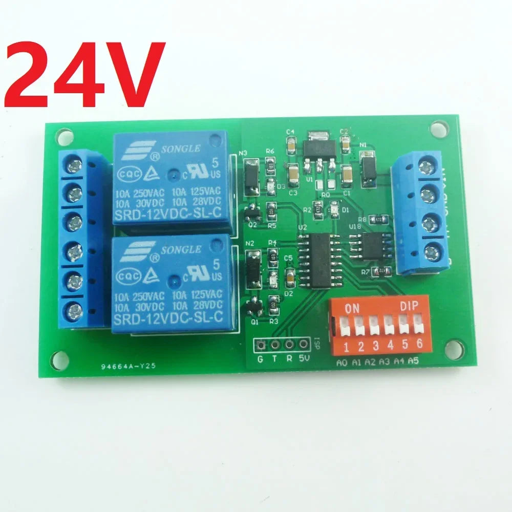
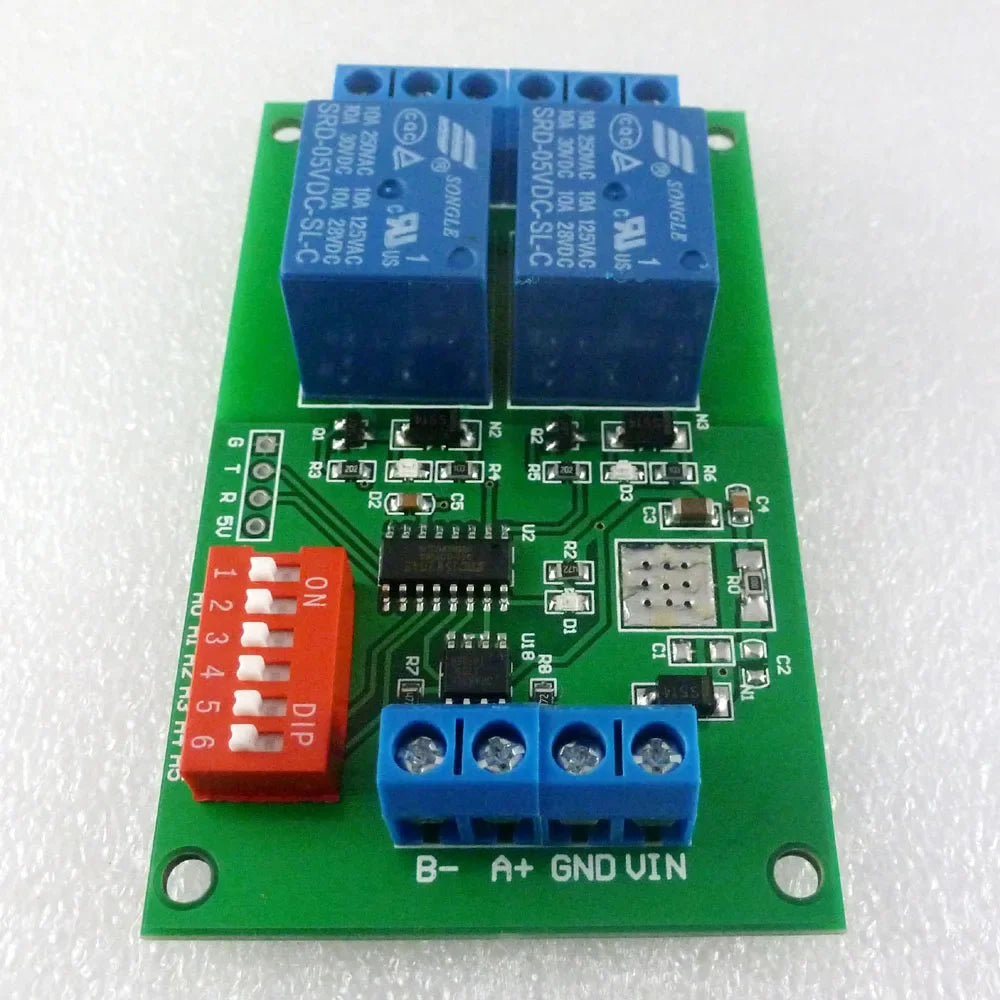
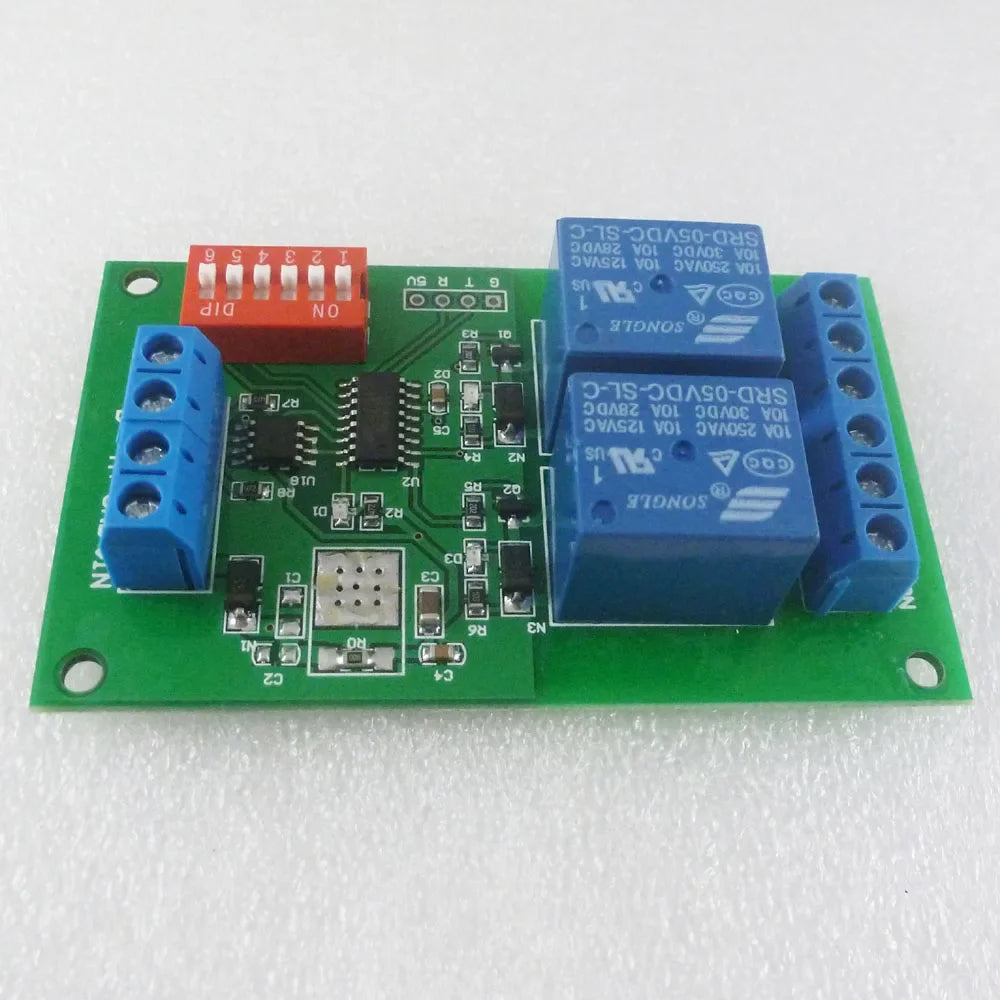
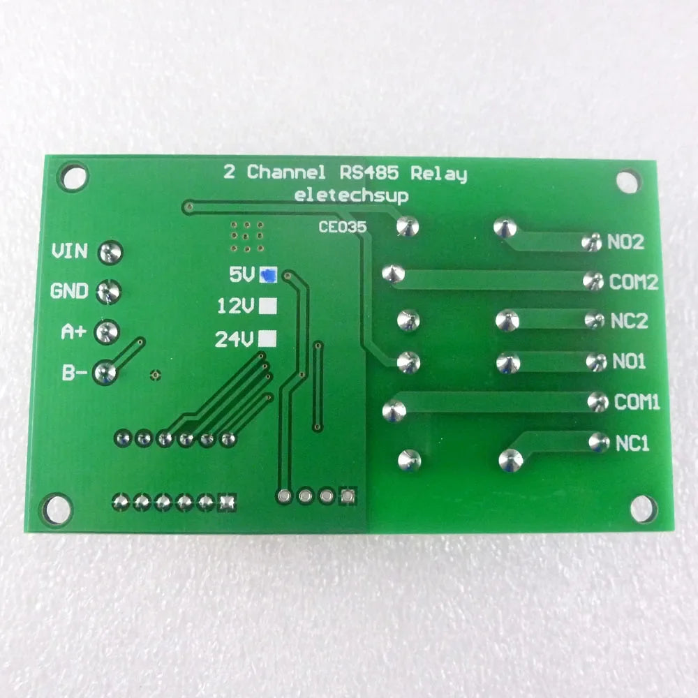
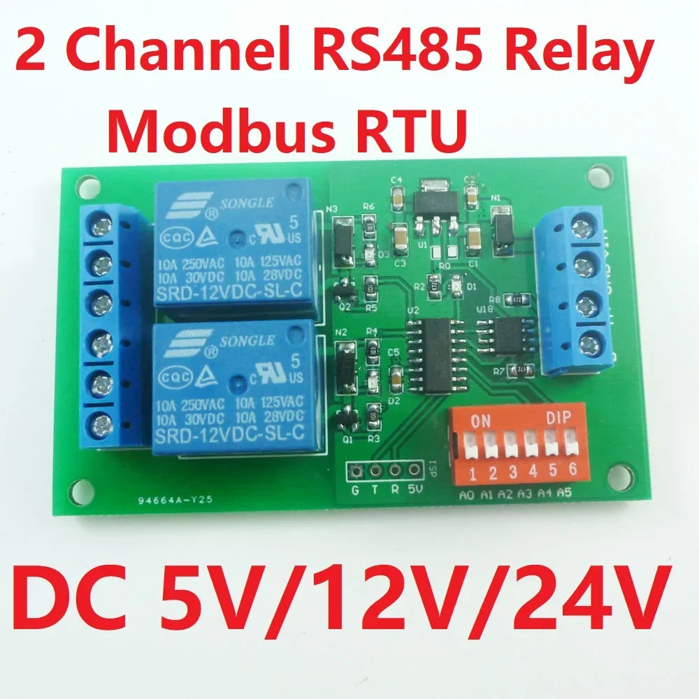
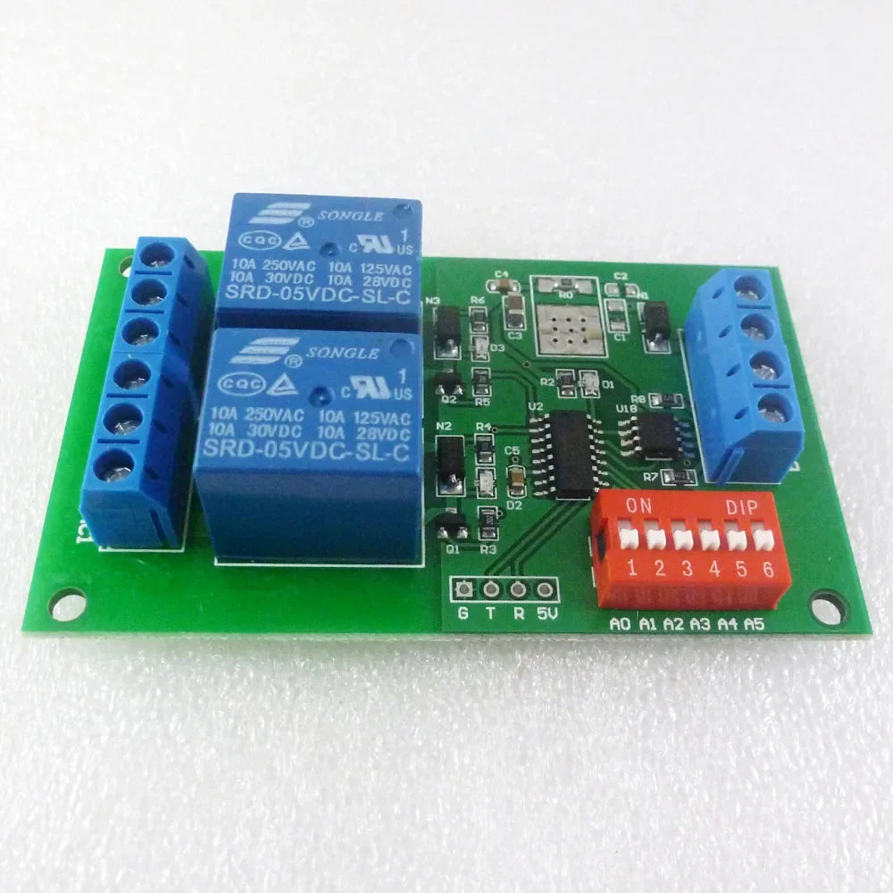
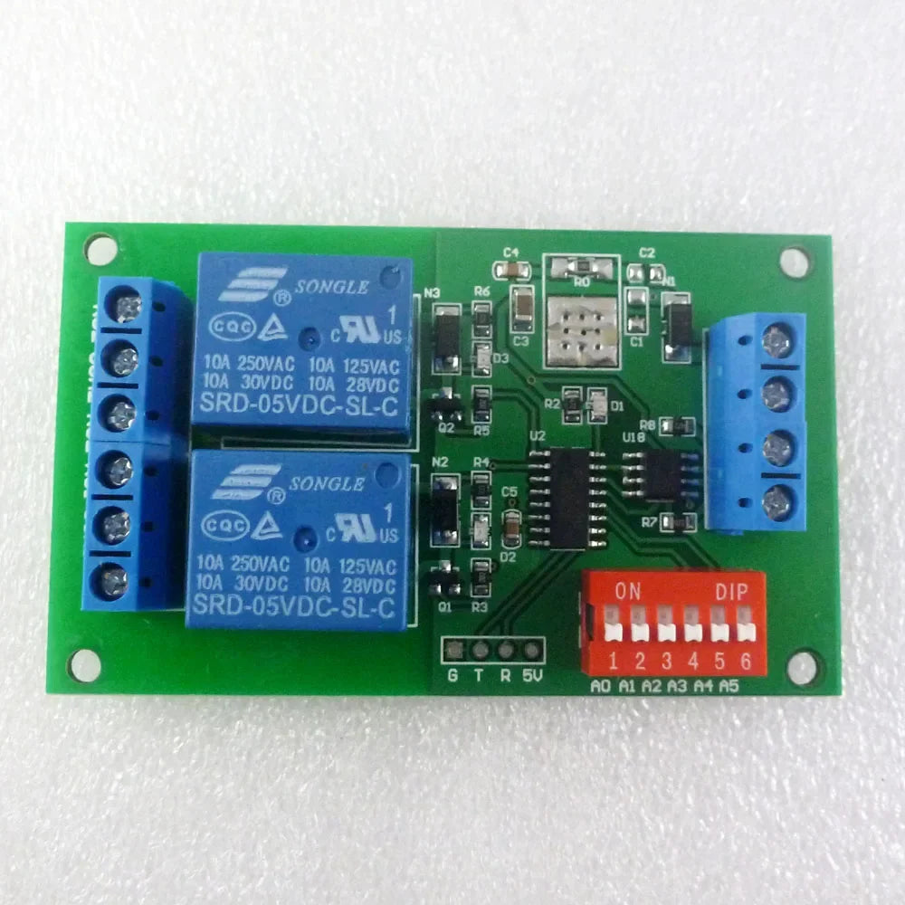
CE035 DC5V 2 CH RS485 Relay Board UART Serial Port Switch Module Modbus AT Command Control For PLC Smart Home Automated Industry
CE035 DC5V 2 CH RS485 Relay Board UART Serial Port Switch Module Modbus AT Command Control For PLC Smart Home Automated Industry
SKU:CE035_24V
1000 in stock
Couldn't load pickup availability
Product Name:
DC 5V 2 CH RS485 Relay Board UART Serial Port Switch Module Modbus AT Command Control For PLC Smart Home Automated Industry
Package inlcuded:
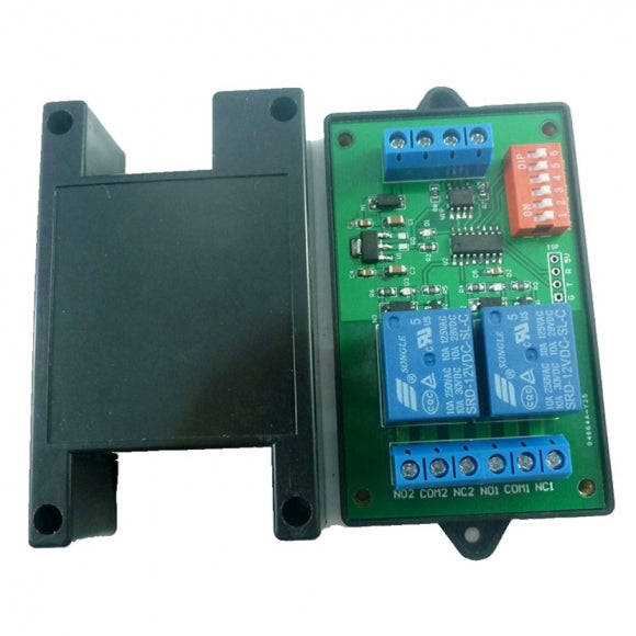
1 x DC 5V/12V24V 2Ch RS485 Modbus AT command Relay Module

Description:
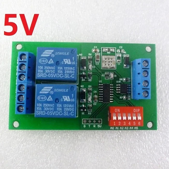
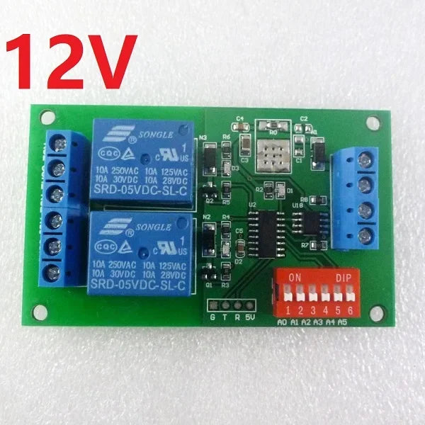
1: DC 5V/12V/24V power supply (
Please choose the voltage you need)
2: Standby current (all relays closed) 7-8MA
3: ''open'' ''close'' ''Momentary'' ''Self-locking'' ''Interlock'' ''Delay'' 6 Commands
4: Two instruction-control mode : AT command and MODBUS command
5: Under the AT command ,the maximum delay is 9999 seconds
Under the MODBUS command ,the maximum delay is 255 seconds
6 AT commands can be made serial HyperTerminal (serial assistant) Enter;
MODBUS commands can be made serial HyperTerminal (serial assistant) OR ''Modbus Poll'' Enter;
7 Under the MODBUS command mode, it can support up to 32 devices in parallel
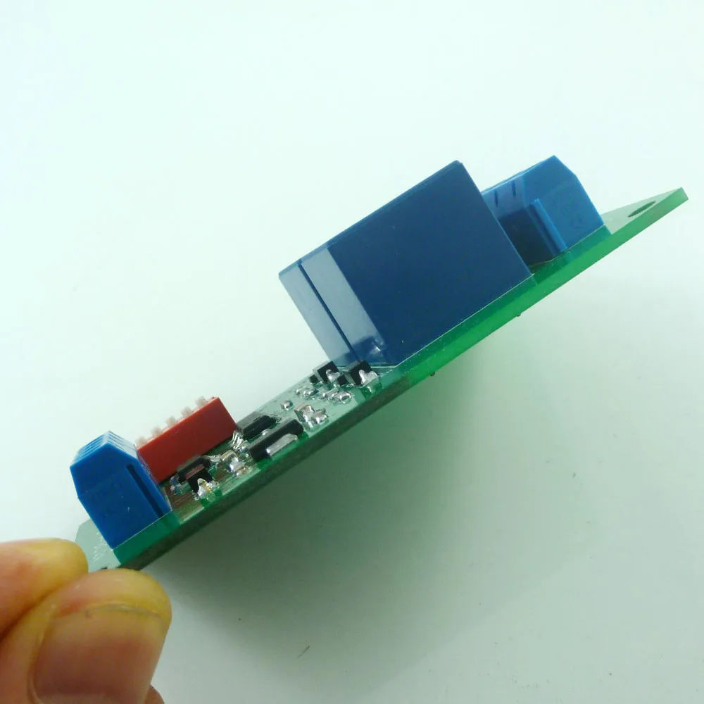
8 Size: 79 * 47.5 * 19.5mm (excluding shell);
9 Weight: 40 g (excluding shell);
10 Maximum load: 10A / 250VAC, 10A / 125VAC, 10A / 30VDC, 10A / 28VDC, 10A / 12VDC
the new version adds the Read Status command (command 03)
Instruction manual Please ask us after the purchase
Application
Automated industry PLC
Smart Home,Home Automation ,Wiser Home;
Identification system;
Motor FW & BW
Light LED power control
Typical applications:
1 AT command mode (A5 = OFF), in this mode can be through the serial HyperTerminal (serial assistant) enter a simple AT command control relay. AT command mode time up to 9999 seconds

2 MODBUS command mode (A5 = ON), you can control a variety of ways: Serial Hyper Terminal Control (need to manually add the CRC), Modbus Poll software control (software automatically add the CRC), PLC or MCU process control


Wiring Diagram:
1 DC 12V control circuit,Wiring diagram below. ''LOAD'' may be camera,LED lights, fans, motors and other DC 12V equipment

2 DC 12V motor reversing control, Wiring diagram below. ''LOAD'' can be Fans, motors, pumps and other DC 12V equipment

3 DC 1-48V OR AC 85-265V control circuit,Wiring diagram below(Note:If not DC 12V load, need another DC 12V power supply). ''LOAD'' may be LED lights, fans, motors Lights, fluorescent lights, solar water heaters and other DC AC equipmen

4 DC 1-48V OR AC 85-265V control circuit,Wiring diagram below(Note:If not DC 12V load, need another DC 12V power supply). ''LOAD'' may be Machine tool ,CNC,3D Printer,LED lights, fans, motors and other DC AC equipment

Test Software(We offer a demo video):
Serial HyperTerminal:

Modbus Poll