Eletechsup Retail Original Factory Store
CE039 4 Channel RS232 Serial Relay Board 12V DC USB UART Remote Switch Controller For Smart Home Car Alarm Farm Equipment
CE039 4 Channel RS232 Serial Relay Board 12V DC USB UART Remote Switch Controller For Smart Home Car Alarm Farm Equipment
SKU:DC5V
10000 in stock
Couldn't load pickup availability
Package inlcuded:
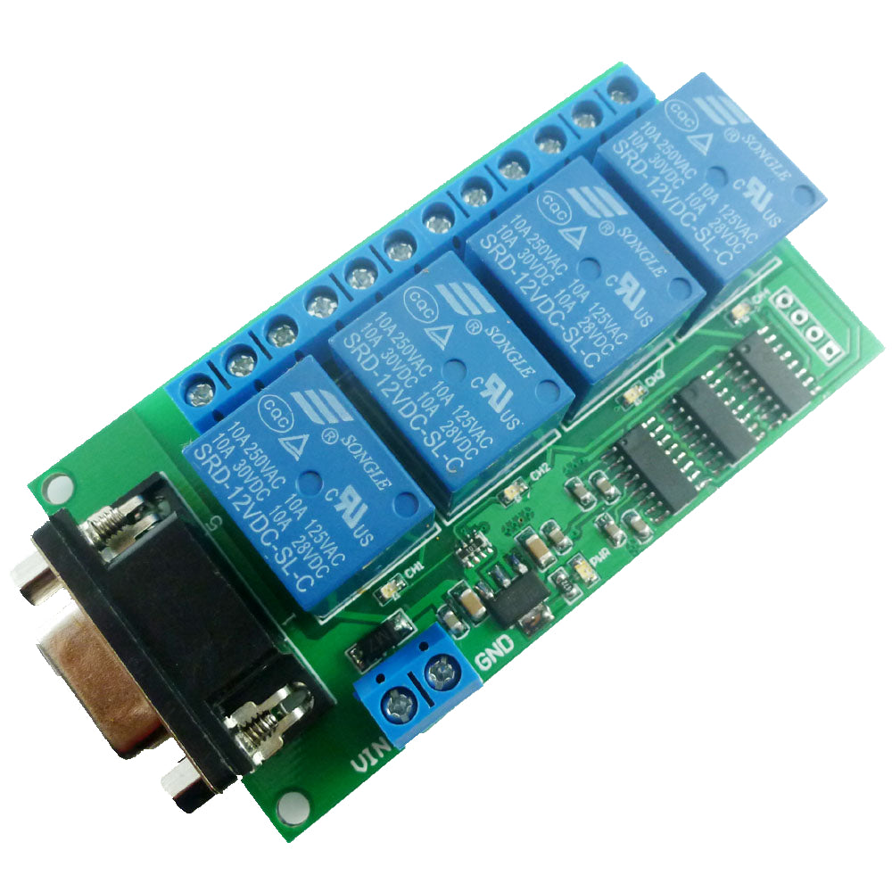
1 x DC 12V 4Ch RS232 Relay Board


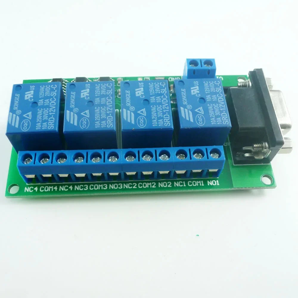
Printing of PCB board is wrong, the correct printing is:
NO4 COM4 NC4 NO3 COM3 NC3 NO2 COM2 NC2 NO1 COM1 NC1
Description:
4 Channel Relay Module;
Power input: DC 12V(8.5-13.5V).
Standby current (all relays closed) 18MA, 1 relay open 50MA, 2 relays open 81MA, 3 relays open 110MA, 4 relays open 140MA
PC Serial ports RS232 Control Relay;
Power indicator : LED lights;
Output indication : relay output with LED indicators,easy to see working status of the relay;
Communication protocol: UART protocol communication, baud rate 9600kpbs, 8 data bits, one stop bit, no parity. Each data frame contains eight bytes. Two-way data transmission.
Baud rate 9600kbps, 8 data bits, one stop bit, no parity. Each data frame contains eight bytes.
Size :
90mm*47mm*19mm
Weight : 62g
For more information, please contact me
1 Control commands:
1. Reading status(reading the satus of the relay (on/off))
55 56 00 00 00 00 00 AB
2.Relay open (issue this command,Relay open,COM connect to NO)
Channel 1 : 55 56 00 00 00 01 01 AD
Channel 2 : 55 56 00 00 00 02 01 AE
Channel 3 : 55 56 00 00 00 03 01 AF
Channel 4 : 55 56 00 00 00 04 01 B0
3. Relay close (issue this command,Relay close,COM disconnect NO,and COM connect to NC)
Channel 1 : 55 56 00 00 00 01 02 AE
Channel 2 : 55 56 00 00 00 02 02 AF
Channel 3 : 55 56 00 00 00 03 02 B0
Channel 4 : 55 56 00 00 00 04 02 B1
4. Relay toggle(Relay status reversal,if COM connect to NO,this commands will Disconnect COM to NO and Reverse COM connect to NC,and vice versa)
Channel 1 : 55 56 00 00 00 01 03 AF
Channel 2 : 55 56 00 00 00 02 03 B0
Channel 3 : 55 56 00 00 00 03 03 B1
Channel 4 : 55 56 00 00 00 04 03 B2
5. Relay momentary(Relay COM connect to NO,disconnect after 200MS)
Channel 1 : 55 56 00 00 00 01 04 B0
Channel 2 : 55 56 00 00 00 02 04 B1
Channel 3 : 55 56 00 00 00 03 04 B2
Channel 4 : 55 56 00 00 00 04 04 B3
6. Relay Interlock
Channel 1 : 55 56 00 00 00 01 05 B1
Channel 2 : 55 56 00 00 00 02 05 B2
Channel 3 : 55 56 00 00 00 03 05 B3
Channel 4 : 55 56 00 00 00 04 05 B4
Once issue a command,will have a return fame,7th byte of return fame mean the satus of realy.
2 return command
1.Return relay open(return this command,mean COM connect to NO)
Channel 1 : 33 3C 00 00 00 01 01 71
Channel 2 : 33 3C 00 00 00 02 01 72
Channel 3 : 33 3C 00 00 00 03 01 73
Channel 4 : 33 3C 00 00 00 04 01 74
2.Return relay close(return this command,mean COM disconnect NO , and COM connect to NC)
Channel 1 : 33 3C 00 00 00 01 02 72
Channel 2 : 33 3C 00 00 00 02 02 73
Channel 3 : 33 3C 00 00 00 03 02 74
Channel 4 : 33 3C 00 00 00 04 02 75
Instruction manual Please ask us after the purchase
Application
Remote control, remote measurement system;
Wireless meter
;
Smart Home,Home Automation ,Wiser Home;
Access control
;
Identification system
;
Data collection;
IT household appliance
;
Intelligence household appliance;
Baby monitoring system;
Typial application :
1 DC 12V control circuit,Wiring diagram below. ''LOAD'' may be LED lights, fans, motors and
other DC 12V equipment

2 DC 1-48V OR AC 85-265V control circuit,Wiring diagram below(Note:If not DC 12V load, need another DC 12V power supply). ''LOAD'' may be LED lights, fans, motors and other DC AC equipment

3 DC 1-100V OR AC 85-265V control circuit,Wiring diagram below(Note:If not DC 12V load, need another DC 12V power supply). ''LOAD'' may be Machine tool ,CNC,3D Printer,LED lights, fans, motors and other DC AC equipment

Test Software:(Only support win xp (32/62) win 7 (32/62) Operating System)