Eletechsup Original Factory Official Store
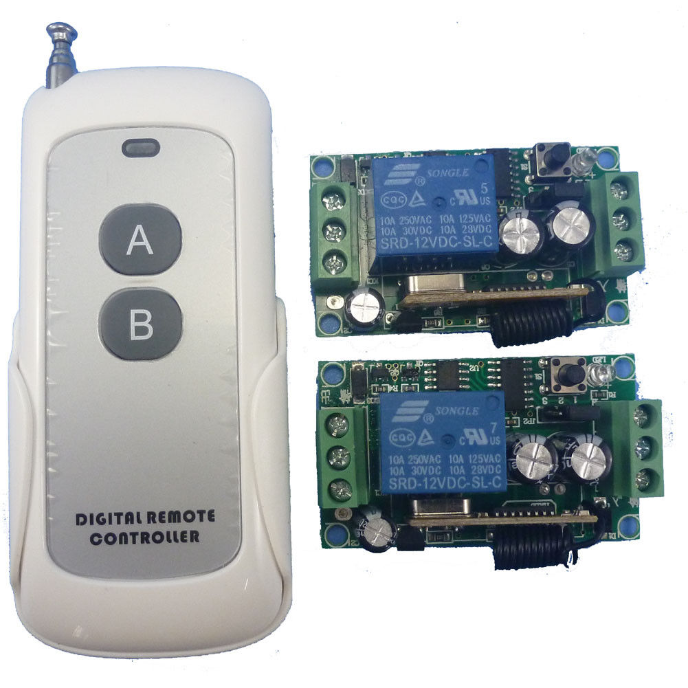
AK029 DC12V 1PCS RF Wireless Remote Relay Control Switch System 2PCS Receivers 433M
AK029 DC12V 1PCS RF Wireless Remote Relay Control Switch System 2PCS Receivers 433M
SKU:AK029*2+TB423*1
1000 in stock
Couldn't load pickup availability
Technical indicators:
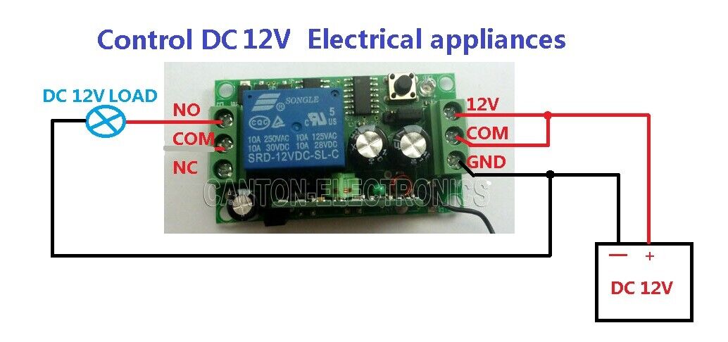
1.operating voltage: DC 12V ;
9. Pls connect the receiver modules properly before power supply ;
10: 1 chanels;
11: Learning function (can works with EV1527 and PT2262 remote , can store 16 pcs different code remote );
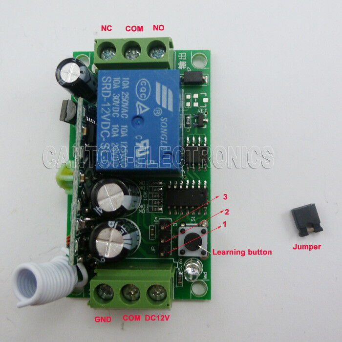
Output:
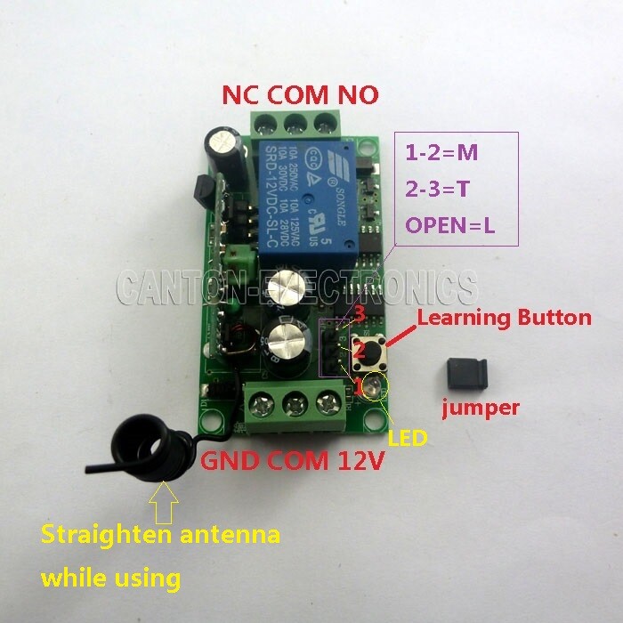
A.singnal Inter-locking (Latch)----connect 2 and 3 ;
B.singnal Self-locking (Toggle) ---- connect 1 and 2 ;
C.singnal Non-locking (Momentary ) ---- All disconnect ;
· Toggle : Press->On; Press again->Off ;
· Latched : Press->On; Press other button->Off ;
· Momentary : Press and hold->On; Release->Off ;
Relay mode :
- Normally-open (NO) contacts connect the circuit when the relay is activated; the circuit is disconnected when the relay is inactive. It is also called a Form A contact or "make" contact. NO contacts may also be distinguished as "early-make" or NOEM, which means that the contacts close before the button or switch is fully engaged.
- Normally-closed (NC) contacts disconnect the circuit when the relay is activated; the circuit is connected when the relay is inactive. It is also called a Form B contact or "break" contact. NC contacts may also be distinguished as "late-break" or NCLB, which means that the contacts stay closed until the button or switch is fully disengaged.
Learning method and steps
1. Keep pressing learnig key on receiver board , release the button when LED is off , enter the learning state ;
2. Press any key on remote control within 5 seconds , LED flash 3 times and then turn on , then it have success in learning .
Clear the deposit information
Keep Pressing Learning Key , LED turns off , Wait 10 Seconds , LED turn on , that deposited information has been successfully cleared ;
Features / Specifications :
Technical Data :

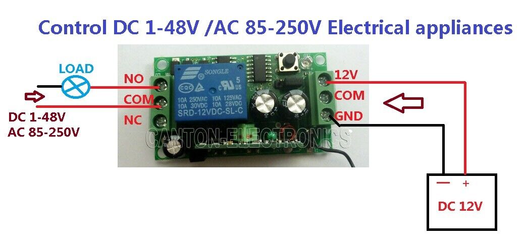
Wiring Diagram 2:
DC 1-48V OR AC 85-265V control circuit,Wiring diagram below(Note:If not DC 12V load, need another DC 12V power supply). "LOAD" may be LED lights, fans, motors and other DC AC equipment