Eletechsup Factory store
OP71A04 4ch 3.3V 5V 12V 24V Digital Logic Level Conversion Module PNP NPN to NPN Optical Isolation Board for Arduiuo NANO STM32 AVR
OP71A04 4ch 3.3V 5V 12V 24V Digital Logic Level Conversion Module PNP NPN to NPN Optical Isolation Board for Arduiuo NANO STM32 AVR
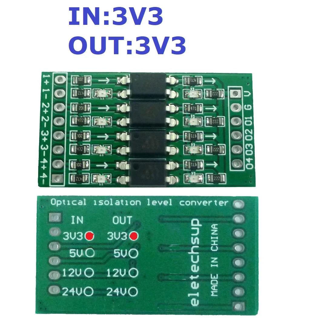
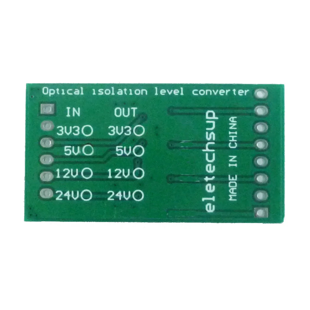
SKU:OP71A04_3V3_3V3
100 in stock
Couldn't load pickup availability
OP71A04 from eletechsup
Product Name: 4ch 3.3V 5V 12V 24V Digital Logic Level Conversion Module PNP/NPN to NPN Optical Isolation Board for Arduiuo UNO NANO STM32 AVR
Packing included:
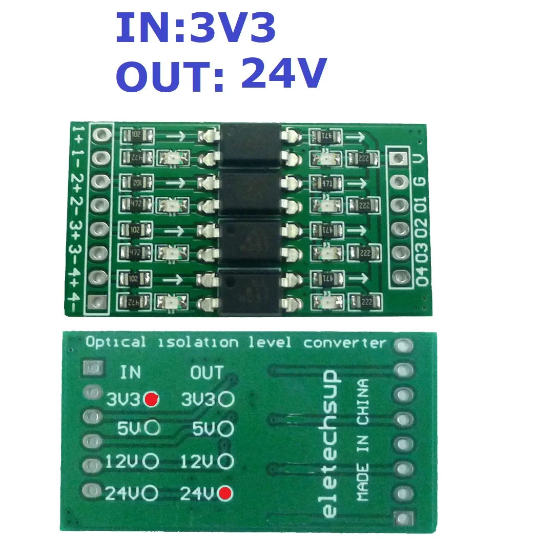
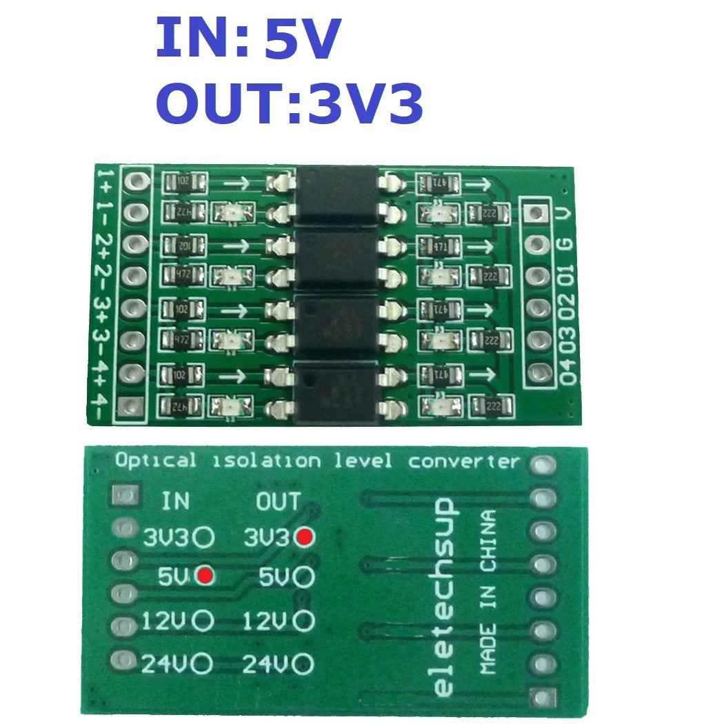
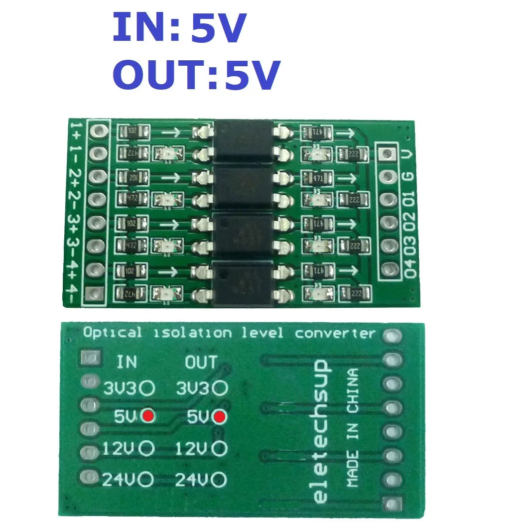
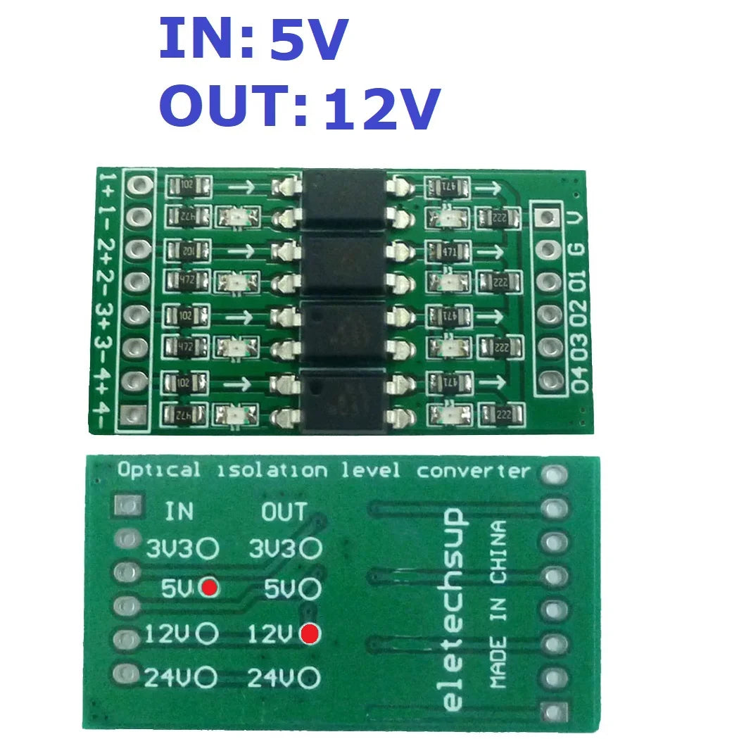
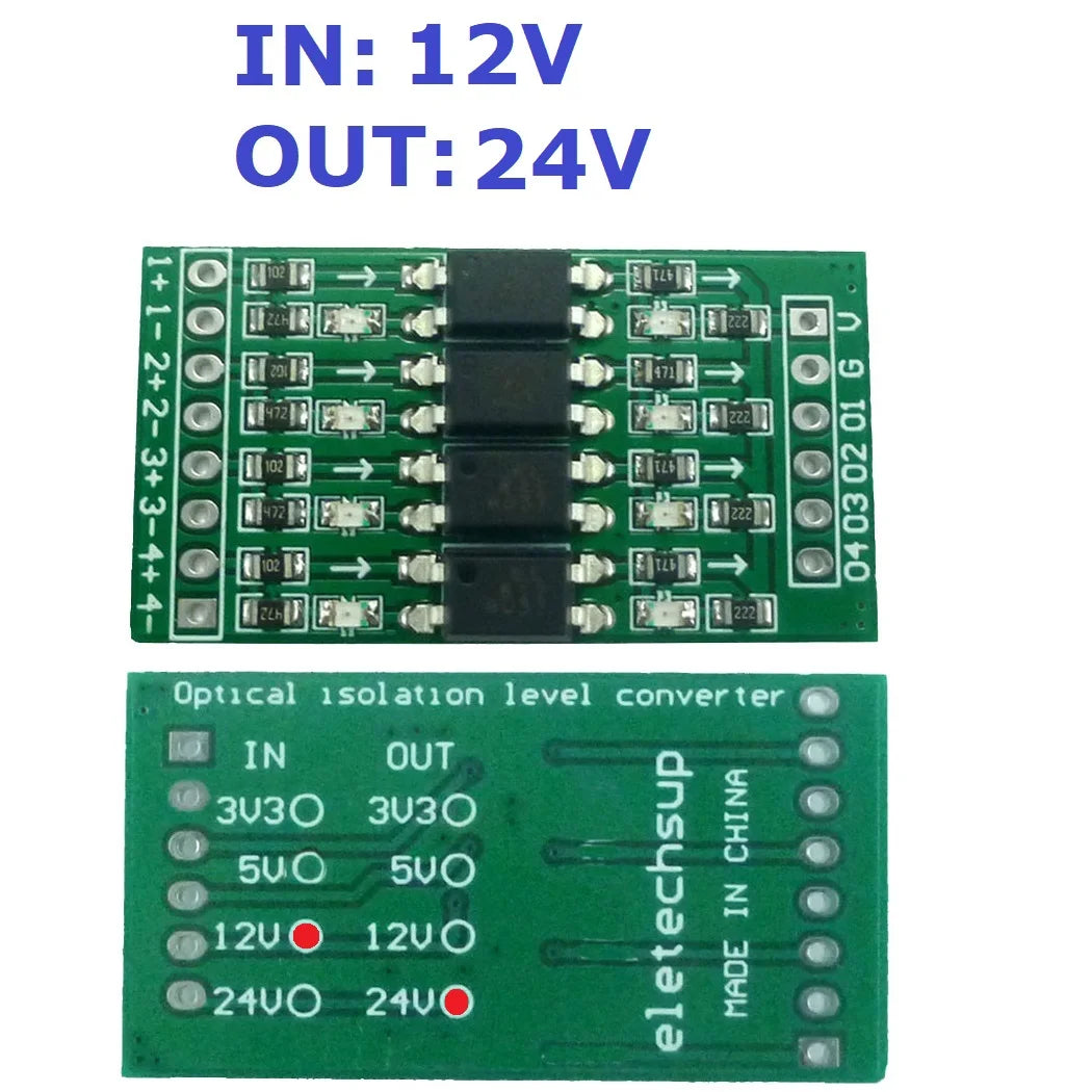
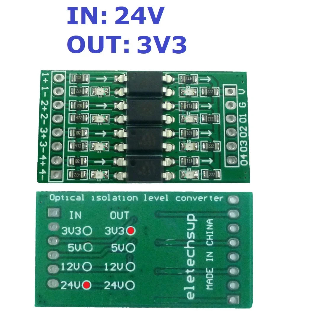
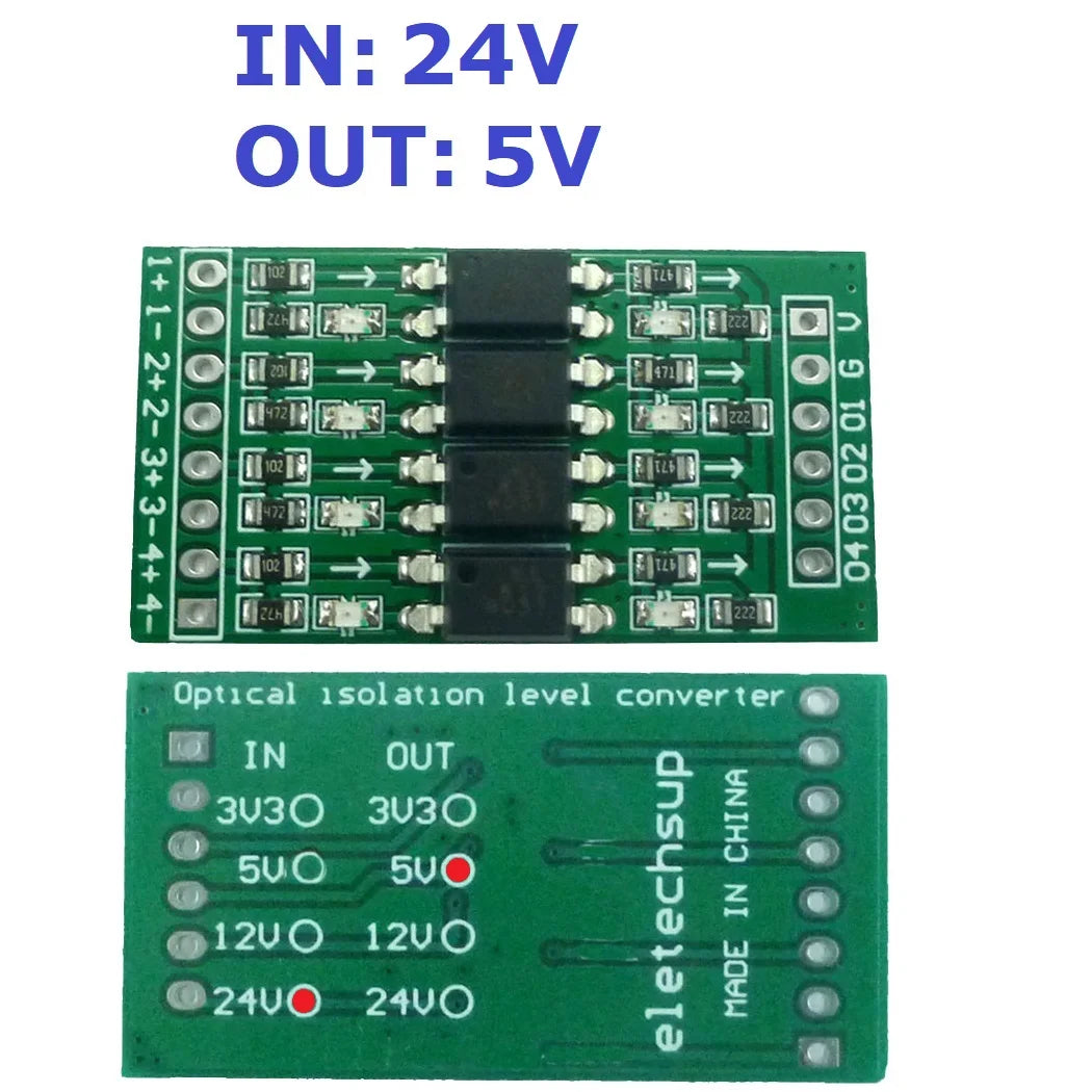
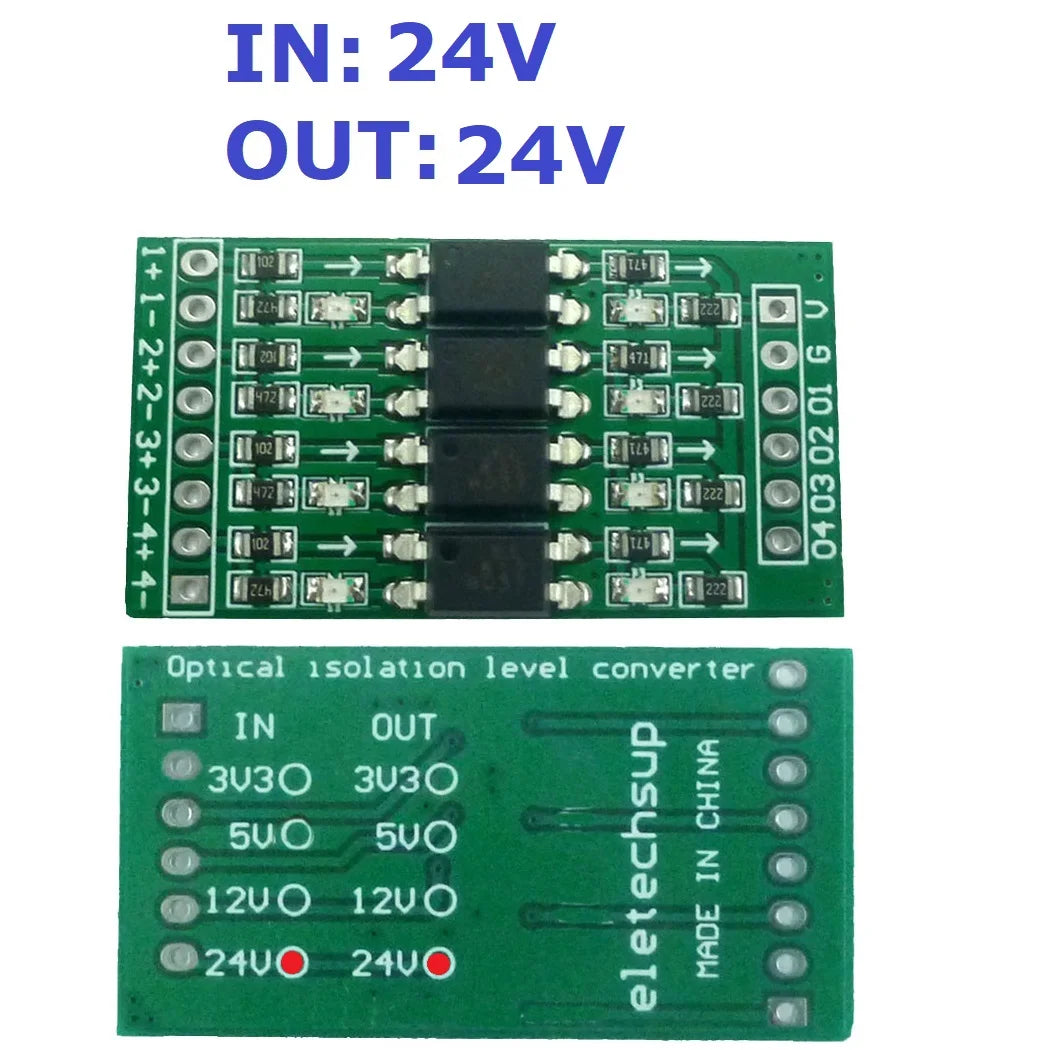
1 PCS 4-chanels 3.3V 5V 12V 24V to photoelectric isolation logic level conversion module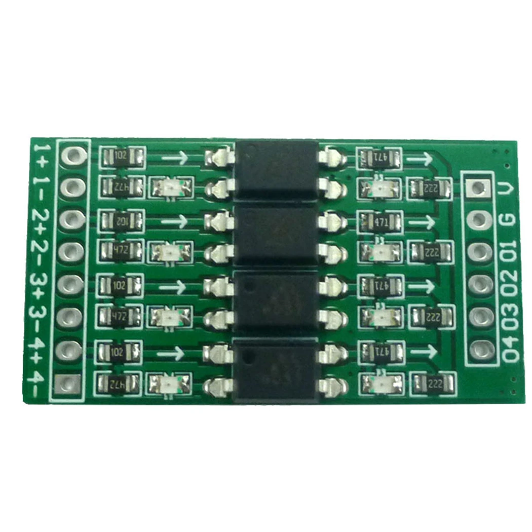
Features
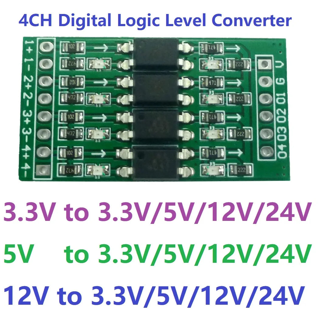
1. Multiple usage Used for signal isolation, PLC level conversion, PNP/NPN to PNP signal, signal level voltage conversion, etc.
2. Use original brand new Taiwanese coupler
3. Limit switching frequency up to 10KHZ
4 for Arduiuo NANO UNO esp8266 raspberry pi
5. Size:38mm*20mm*5mm
6. Weight:3.9g
Module wiring terminal and definition:
|
Function |
Label |
Instruction |
|
Signal Input |
1+ |
The first signal input anode |
|
1- |
The first signal input cathode |
|
|
2+ |
The second signal input anode |
|
|
2- |
The second signal input cathode |
|
|
3+ |
The third signal input anode |
|
|
3- |
The third signal input cathode |
|
|
4+ |
The fourth signal input anode |
|
|
4- |
The fourth signal input cathode |
|
|
Power Input |
VCC |
DC power anode(*) |
|
GND |
DC power supply cathode |
|
|
Signal Output |
O1 |
The first signal output |
|
O2 |
The second signal output |
|
|
O3 |
The third signal output |
|
|
O4 |
The fourth signal output |
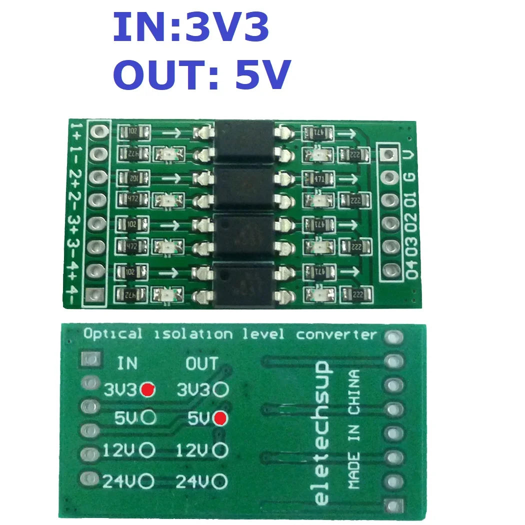
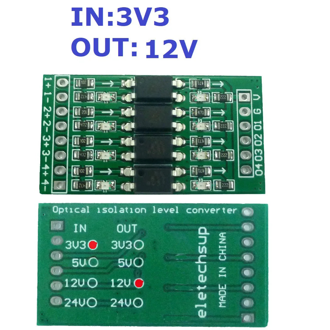
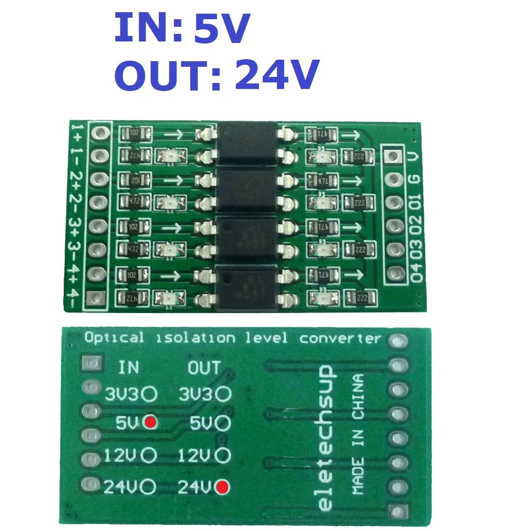
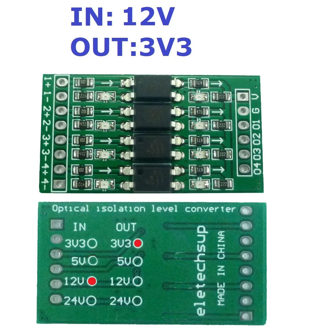
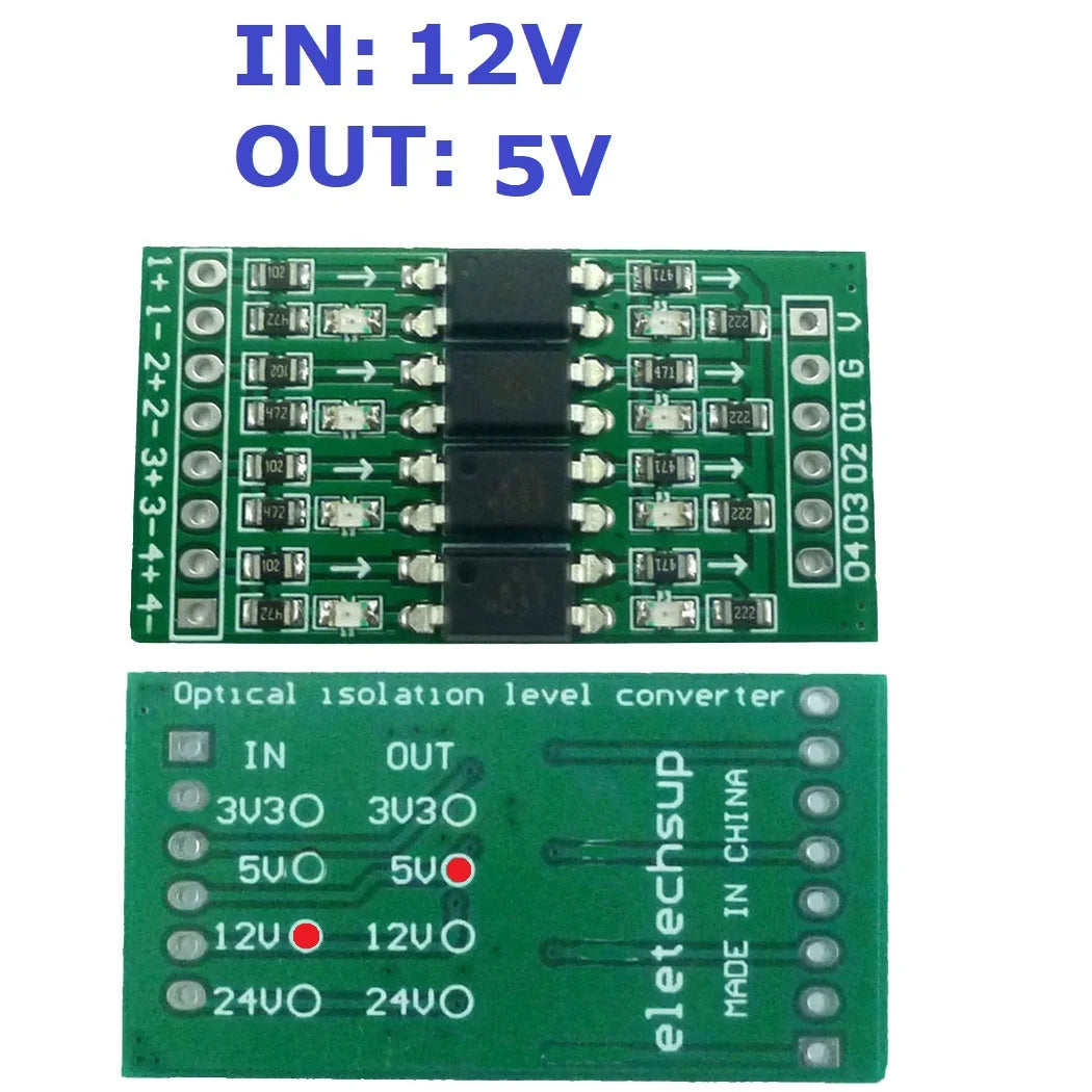
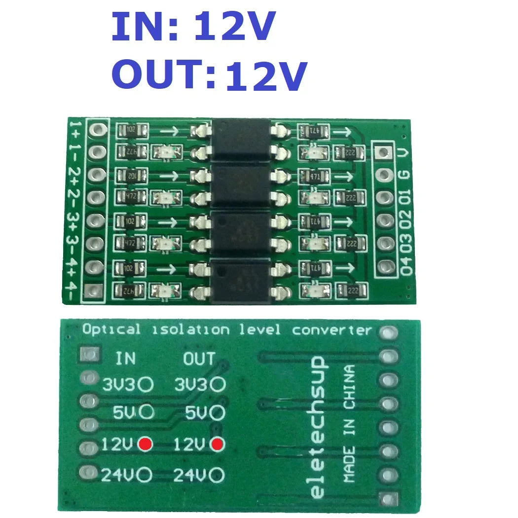
(*):The DC power supply is the same as the signal output voltage. For example, if the signal is from 3.3V to 5V, then VCC=5V input.
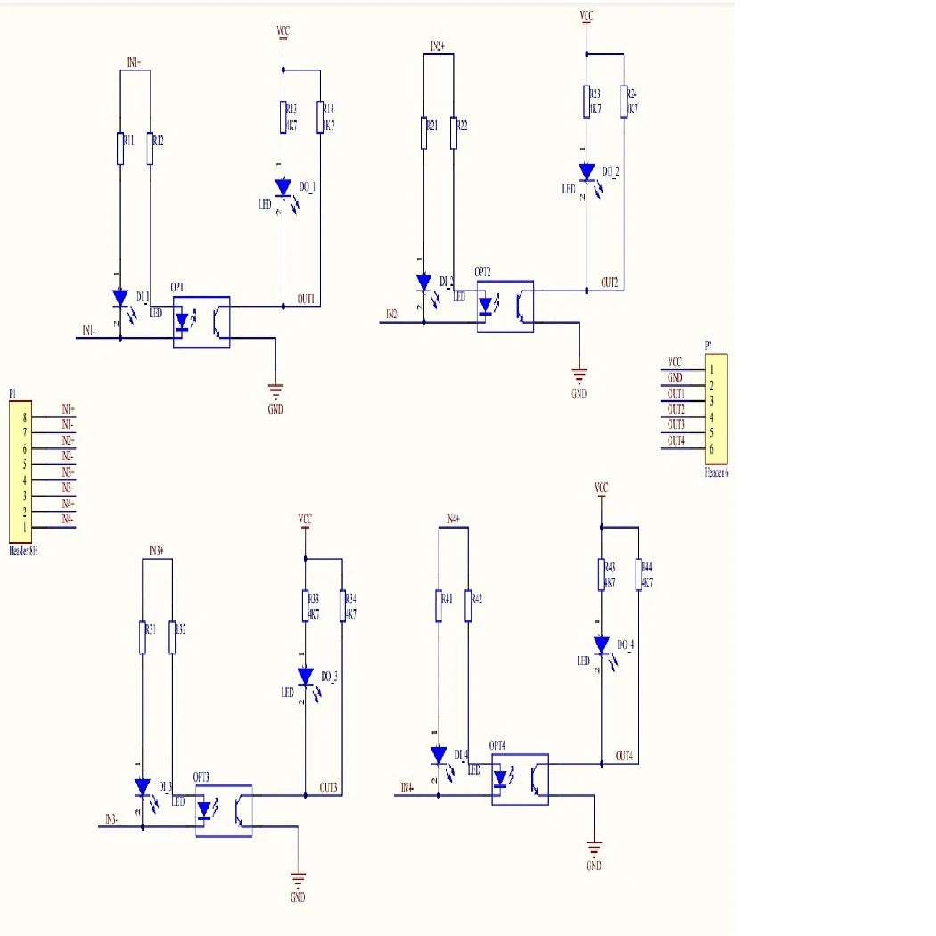
Schematic diagram of the internal structure of the module:

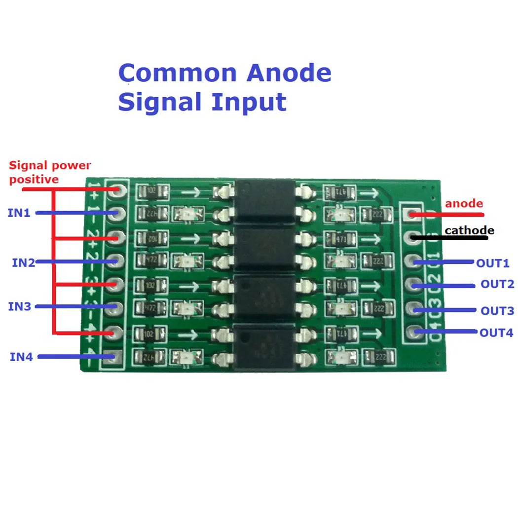
Module connection diagram:

Common anode signal(NPN) input
|
Input and output truth table |
|
|
Signal Input |
Signal Output |
|
H(High level)5V |
L(Low level)0V |
|
L(Low level)0V |
H(High level)24V |
Note:In this example, the anode of the signal power supply is DC +5v, and the anode of the module power supply is DC +24V
Common cathode signal input:

Common cathode signal(PNP) input:
|
Input and output truth table |
|
|
Signal Input |
Signal Output |
|
H(High level)5V |
H(High level)24V |
|
L(Low level)0V |
L(Low level)0V |
Note:In this example,Module power supply is DC+24V
Differential signal input:

|
Input and output truth table |
|
|
Signal Input |
Signal Output |
|
H(High level) |
H(High level)24V |
|
L(Low level) |
L(Low level)0V |
Note:In this example,Module power supply is DC+24V