Eletechsup Original Factory Official Store
PLL ASK OOK Wireless RF Wireless LINK Transceiver Founction RX TX Modules 433MHZ
PLL ASK OOK Wireless RF Wireless LINK Transceiver Founction RX TX Modules 433MHZ
SKU:BX005*1+BX011*1
Low stock: 8 left
Couldn't load pickup availability
PLL ASK OOK Wireless RF Wireless LINK Transceiver Founction RX TX Modules 433MHZ
Operating frequency (MHz): 433.92MHz ;
Low power consumption : 3.3V @ 433.92MHz, 6.0mA / 3.3V @315MHz,4.8mA;
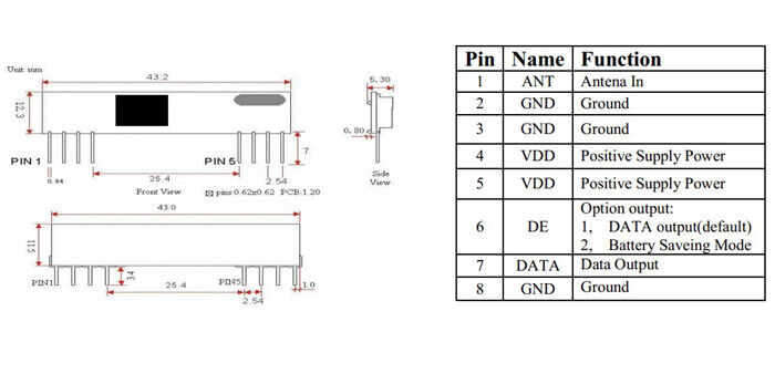
Frequency tolerance: ±50 KHz;The rang can be up to 300-500m matching with XLC-RM08;Operating temperature: -40℃~+80℃;Small Size with Size of PCB: 11x16x5.5MM;Bit rate: <3kbps;
Sometimes in embedded design you may want to go wireless. Might be you will want to log various readings of remotely placed sensors, or simply build a remote control for robot or car alarm system.
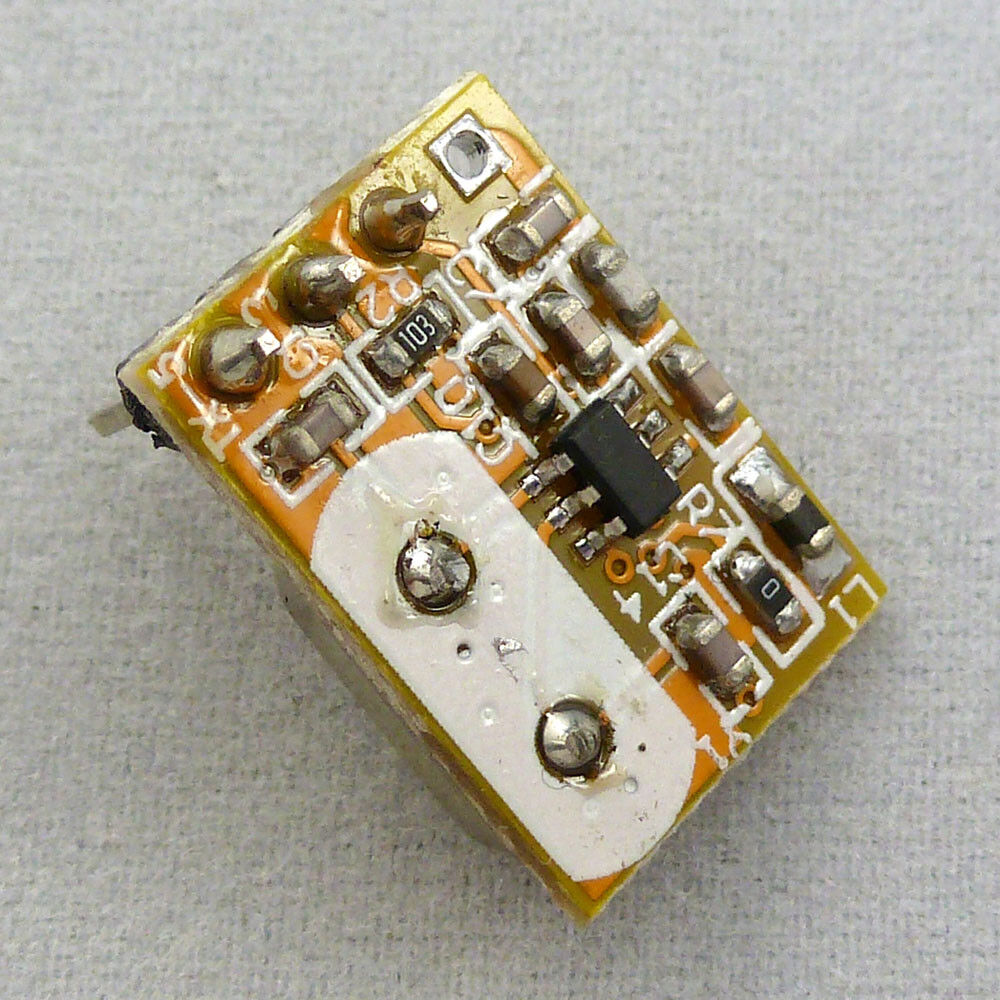
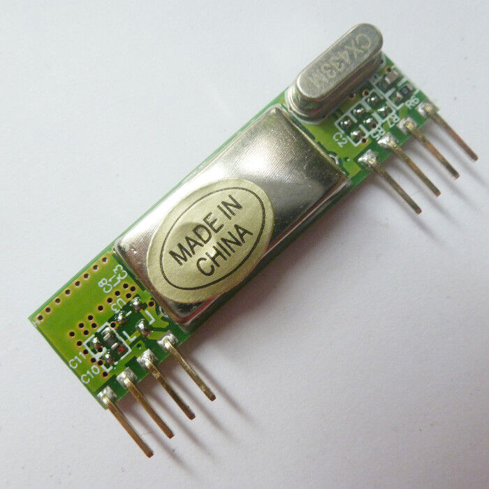
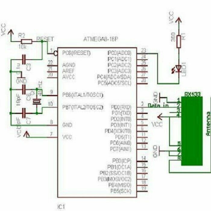
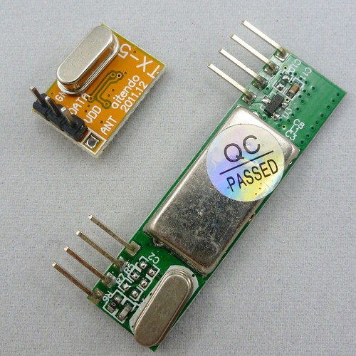
Radio communications between two AVR microcontrollers can be easy when specialized modules are used. Lets try to run very well known RF modules TX433 and RX433 that (or similar) can be found almost in every electronics shop and pair of them cost about 6.99USD .
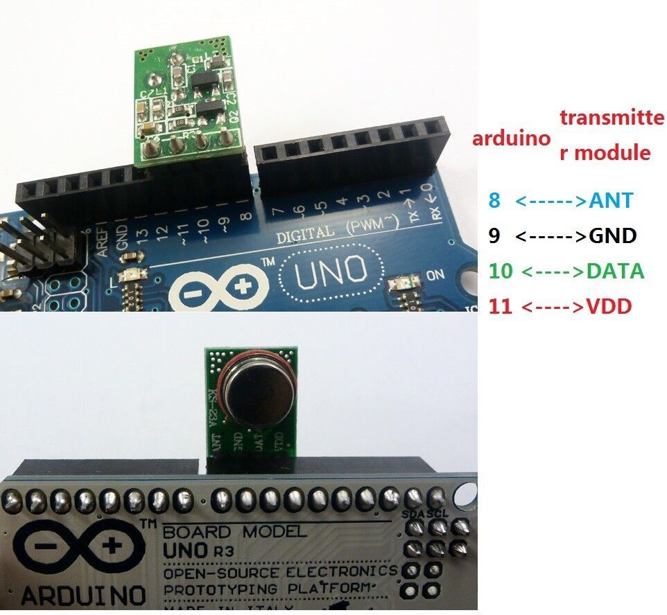
Transmitter and receiver modules are tuned to work correctly at 433.92MHz. Transmitter can be powered from 1.8-3.6V power supply while receiver accepts 5V. 5V is common for AVR microcontrollers so no problems with interfacing. Modules don't require addition components – just apply power and connect single data line to send information to/from and that's it. For better distances apply 30 – 35cm antennas. Modules use Amplitude-Shift Keying(ASK) modulation method and uses 1MHz bandwidth.
I have constructed two separate circuits for testing on Atmega8 microcontrollers.
Lets move on to software part. Radio transmission is a bit more complicated than wired communications because you never know what radio signals are present on air. So all matters how transmitted signal is encoded. And this is a part where you have many choices: use hardware encoding like USART or write your own based on one of many ending methods like NRZ, Manchester etc. In my example I have used AVR USART module to form data packs. Using hardware encoders solves many problems like synchronization, start and stop, various signal checks. But as long as I was practising you cannot rely on plain USART signal. Here you can actually improvize by adding various checks and so on.
I decided to form 4 byte data packages in order to send one byte information. These include:
-
one dummy synchronization byte (10101010);
-
one address byte – in case there are more receivers(or transmitters);
-
one data byte;
-
and checksum which is actually a sum of address and data(address+data).
Why did I use a dummy byte at the beginning of package. Simply I noticed, that when transmitter doesn't transmit any data – receiver catches various noises that come from power supply or other sources because receiver likes adjust its input gain depending on input signal level. First byte tunes receiver to accept normal signal after then address byte, data and checksum can be read more reliably. Probably with different transmission modules you may exclude this dummy byte.
Ttransmitter program for AVR Atmega8:
#include
#include
#ifndef F_CPU
//define cpu clock speed if not defined
#define F_CPU 8000000
#endif
//set desired baud rate
#define BAUDRATE 1200
//calculate UBRR value
#define UBRRVAL ((F_CPU/(BAUDRATE*16UL))-1)
//define receive parameters
#define SYNC 0XAA// synchro signal
#define RADDR 0x44
#define LEDON 0x11//switch led on command
#define LEDOFF 0x22//switch led off command
void USART_Init(void)
{
//Set baud rate
UBRRL=(uint8_t)UBRRVAL; //low byte
UBRRH=(UBRRVAL>>8); //high byte
//Set data frame format: asynchronous mode,no parity, 1 stop bit, 8 bit size
UCSRC=(1<
(0<
//Enable Transmitter and Receiver and Interrupt on receive complete
UCSRB=(1<
}
void USART_vSendByte(uint8_t u8Data)
{
// Wait if a byte is being transmitted
while((UCSRA&(1<
// Transmit data
UDR = u8Data;
}
void Send_Packet(uint8_t addr, uint8_t cmd)
{
USART_vSendByte(SYNC);//send synchro byte
USART_vSendByte(addr);//send receiver address
USART_vSendByte(cmd);//send increment command
USART_vSendByte((addr+cmd));//send checksum
}
void delayms(uint8_t t)//delay in ms
{
uint8_t i;
for(i=0;i
_delay_ms(1);
}
int main(void)
{
USART_Init();
while(1)
{//endless transmission
//send command to switch led ON
Send_Packet(RADDR, LEDON);
delayms(100);
//send command to switch led ON
Send_Packet(RADDR, LEDOFF);
delayms(100);
}
return 0;
}
In my case I used UART 1200 baud rate. It may be increased or decreased depending on distance and environment. For longer distances lower baud rates works better as there is bigger probability for transmission errors. Maximum bit rate of transmitter is 8kbits/s what is about 2400 baud. But what works in theory usually do not work in practice. So 1200 baud is maximum what I could get working correctly.
Transmitter sends two commands (LEDON and LEDOFF) to receiver with 100ms gaps. Receiver recognizes these commands and switches LED on or off depending on received command. This way I can monitor if data transfer works correctly. If LED blink is periodical – then transmission goes without errors. If there is an error in received data then LED gives shorter blink.
Receiver program code:
#include
#include
#include
#ifndef F_CPU
//define cpu clock speed if not defined
#define F_CPU 4000000
#endif
//set desired baud rate
#define BAUDRATE 1200
//calculate UBRR value
#define UBRRVAL ((F_CPU/(BAUDRATE*16UL))-1)
//define receive parameters
#define SYNC 0XAA// synchro signal
#define RADDR 0x44
#define LEDON 0x11//LED on command
#define LEDOFF 0x22//LED off command
void USART_Init(void)
{
//Set baud rate
UBRRL=(uint8_t)UBRRVAL; //low byte
UBRRH=(UBRRVAL>>8); //high byte
//Set data frame format: asynchronous mode,no parity, 1 stop bit, 8 bit size
UCSRC=(1<
(0<
//Enable Transmitter and Receiver and Interrupt on receive complete
UCSRB=(1<
//enable global interrupts
}
uint8_t USART_vReceiveByte(void)
{
// Wait until a byte has been received
while((UCSRA&(1<
// Return received data
return UDR;
}
ISR(USART_RXC_vect)
{
//define variables
uint8_t raddress, data, chk;//transmitter address
//receive destination address
raddress=USART_vReceiveByte();
//receive data
data=USART_vReceiveByte();
//receive checksum
chk=USART_vReceiveByte();
//compare received checksum with calculated
if(chk==(raddress+data))//if match perform operations
{
//if transmitter address match